Two new ICRF antennas operating in the ion cyclotron radio frequency (ICRF) range have been developed for EAST to overcome the low coupling problem of the original antennas. The original ICRF antennas were limited in their power capacity due to insufficient coupling. The new antenna design takes into account both wave coupling and absorption processes through comprehensive wave coupling and absorption codes, with the dominant parallel wave number k// of 7.5 m−1 at dipole phasing. Through the use of these new ICRF antennas, we are able to achieve 3.8 MW output power and 360 s operation, respectively. The initial experimental results demonstrate the reliability of the antenna design method.
The ion cyclotron radio frequency (ICRF) range wave is widely used in magnetic confinement devices for plasma heating and current drive. The main working principle relies on exciting and coupling fast wave (FW) in plasma via ICRF antenna. As it is well known, the ICRF antenna coupling resistances is of R∝e−Ak//x, where k// is the dominant parallel wave number and x is the width of the FW evanescent layer [1–6]. One of the major challenges for ICRF heating is whether sufficient RF power can be coupled into the plasma core by fast wave. Low k// and narrow width of FW evanescent layer are beneficial to increase the efficiency of power coupling. However, good ICRF wave coupling is not equal to efficient power absorption [7]. Optimizing the power spectrum of the ICRF antenna based on device parameter characteristics is essential.
For EAST tokamak (R0 = 1.85 m, a = 0.45 m, B0 < 3.5 T, Ip ~ 1 MA), ICRF heating is an important auxiliary heating method, which alone has achieved H-mode discharge [8]. Before 2021, two ICRF antennas (B- and I-port) with 25–70 MHz are used on EAST [9, 10]. The B-port antenna consists of toroidal two-loop straps with k// = 12.6 m−1 at dipole phasing, while the I-port antenna features toroidal four-folded straps with k// = 13.6 m−1 at (0, π, 0, π) phasing. But the previous experiment data on EAST have shown that the coupling of these original antennas is insufficient [11, 12]. The low coupling of antenna will increase the standing wave voltage on transmission line and limit the ICRF system power capacity on EAST. The antenna performance can be enhanced by reducing the value of the launched k// through adjustments in phase and the thickness of the FW evanescent layer via gas puffing, the advancement of controlling plasma shape and antenna position [2, 13, 14]. However, advancing the methods of gas puffing, controlling plasma shape, and adjusting antenna position to enhance antenna coupling on EAST faces challenges or constraints due to issues such as impurity sputtering and thermal load. The improvement of the I-port antenna coupling by adjusting phase may decrease the wave heating effect. So the ICRF wave coupling on EAST has been troubled for many years.
The ICRF antenna types mainly include resonant loop antenna [15], loop antenna [16], folded antenna [17] and ITER-like short strap antenna [18]. The resonant loop antenna with electric capacitors is not used for ITER, and the EAST port does not have enough space to accommodate ITER-like antenna. For the new ICRF antenna on EAST, a simple loop strap antenna is proposed and installed in N- and I-ports.
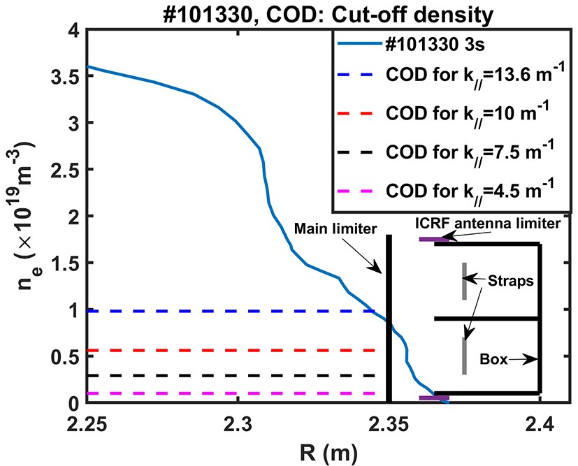
The dominant k// of the ICRF antennas are within the range of 5–15 m−1 at dipole phasing for JET [19], Alcator C-mod [20], ASDEX-U [21] and WEST [22]. The device size and plasma parameters restrict antenna spectrum selection. It is necessary to form an effective process to consider antenna spectrum design. The FW cut-off layer and cut-off densities of ICRF antenna on EAST at different k// are plotted in figure 1. The edge plasma density profile is measured by a microwave reflectometry [23]. The scheme of low dominant k// of antenna seems to be very suitable for increasing coupling, but it is necessary to determine the optimal spectrum to avoid the coaxial mode or impurity sputtering [24].
Figure
1.
The edge plasma profile of EAST #101330 and the FW cut-off densities for different k//.
In the paper, we will elaborate on how to select the antenna spectrum from the perspective of wave coupling and absorption, compare the performance of old and original antennas, and provide the latest experimental results achieved by the new antennas. The experience and methods of spectrum optimization may provide a reference for the design of ICRF antennas in ITER and the Chinese Fusion Engineering Testing Reactor (CFETR).
2.
Theoretical prediction and simulation setup
The physical design of antenna involves the following 3 steps: (1) a quick assessment of the antenna power spectrum through numerical solutions, (2) optimization of power absorption considering different power spectra using TORIC code with a core wave propagation and absorption, and (3) evaluation of antenna coupling through a finite element code based on COMSOL scanning size parameters.
Regarding wave absorption, for the H+ minority resonance and D+ majority ions case the FW absorption rate ηa can be obtained [25]
ηa=1−e−λ,
(1)
where λ=π2ωPDRcnHnDZHZD11+σ2, ωPD=(nDe2mDε0)1/2, σ2=π4(nHnDmDmHZ2HZ2D)2(1−ω2cDω2)2(ωk//vtD)2, the subscripts of D and H represent the ion species, ωp is the plasma oscillation frequency, ωc is the ion cyclotron frequency, ω is the RF wave frequency, R is the major radius, n is plasma density, m is the ion mass, Z is the ion charge, and vt is the velocity ofhot ion. The FW absorption rate is used to assess the ratio ofFW power absorbed by the plasma to the FW power entering the plasma. The high plasma density and ion temperature are beneficial to the wave absorption. Equation (1) is derived based on the single-pass wave absorption by H+ minority fundamental resonance and D+ majority second resonance heating.
On the topic of wave coupling, the FW coupling efficiency can be estimated using the expression: ηc=e−Ak//x, where A is experimentally determined to be 1.5 for EAST [2], and x = 0 represents the radial position of strap. The coupling assessment assumes that the radio wave in the interface of strap is normalized.
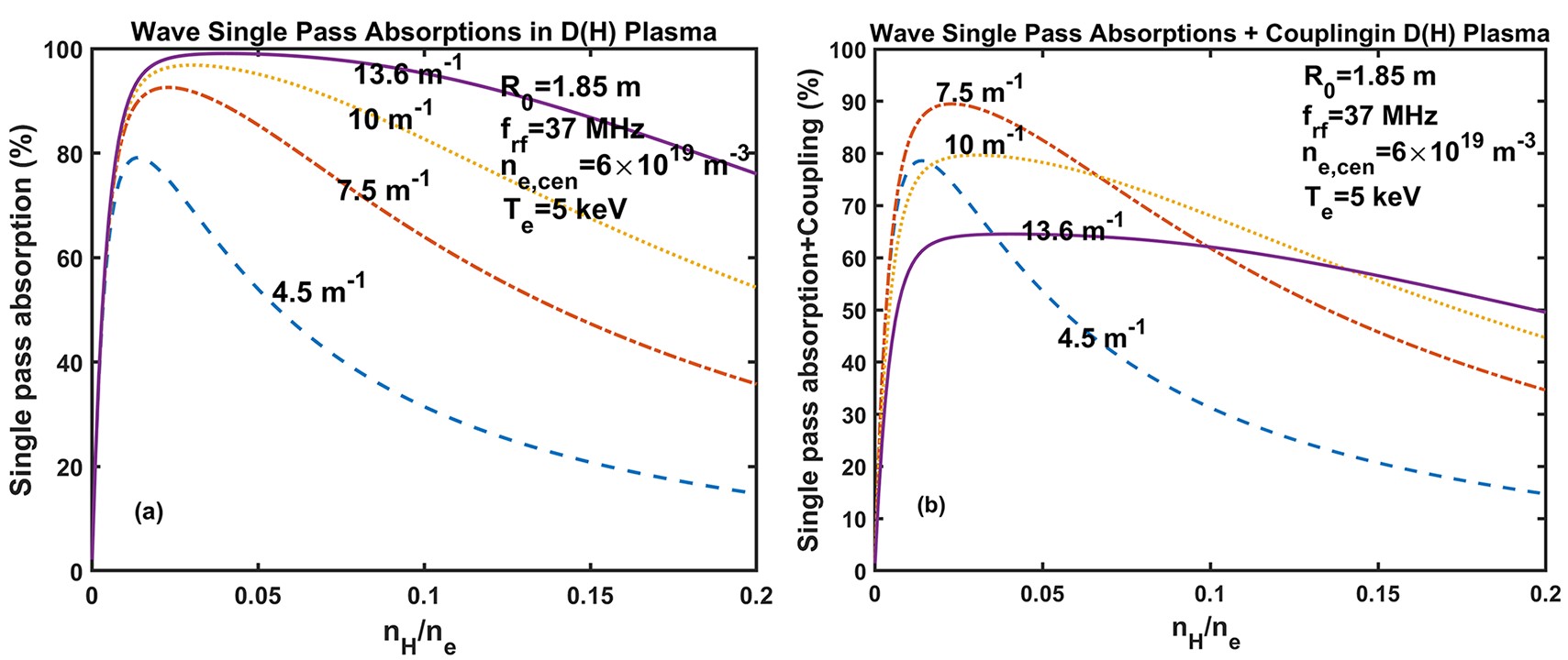
The wave coupling and absorption are combined with η=ηa×ηc. Figure 2 shows the ICRF wave coupling and absorption efficiency with typical parameters for EAST. The ICRF wave exhibits better single-pass absorption at high k//, which is precisely why the original antenna is designed for operation at high k//. However, as shown in figure 2(b), considering the FW coupling efficiency, the FW power coupled into the plasma is not better at high k// as long as the hydrogen concentration remains below 15%. The wave absorption results will be verified using TORIC in the next section.
Figure
2.
(a) ICRF wave single-pass absorption at different hydrogen concentrations (major D), (b) ICRF wave single-pass absorption and antenna coupling at different hydrogen concentrations.
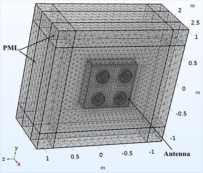
A finite element model of the antenna is built in COMSOL for the antenna coupling simulation, as shown in figure 3. The plasma is modeled as a cold plasma using the Stix tensor [26]. A perfectly matched layer (PML) beyond plasma is applied to simulate the wave single-pass absorption in the plasma core. The dielectric tensor of PML material is defined as [27]:
where εx,y,z is the Stix tensor, Sx,y,z is a stretching function and defined as Sx,y,z=1−4.7i(ρδ)2 for EAST, ρ is the depth of wave propagation in PML, and δ is the depth of PML.
The antenna excitation is achieved by applying a voltage of 45 kV to each coaxial line. The antenna coupling resistance in the COMSOL model is defined as [28]:
Rc=Z0SWR=Z0(1−|Γ|)1+|Γ|,
(3)
where Z0 is the characteristic impedance of transmission line with a value of 30 Ω, Γ represents the reflection coefficient of power at the coaxial port, and SWR is the standing wave voltage.
To compare the experiment results, the coupling resistance is expressed in terms of RF power and voltage on the transmission line by measurement. The measured antenna resistance is
Rm=2PZ20V2max,
(4)
where the value of Z0 is 30 Ω, Vmax is the maximum voltage on the transmission line near antenna. The measured antenna resistance includes the impedance of the antenna with both vacuum and plasma loads. The vacuum load of antenna, which is between 0.2 and 0.4 Ω, is ignored in the calculation.
3.
Optimization of the ICRF antenna
3.1
Wave absorption dependence on spectrum
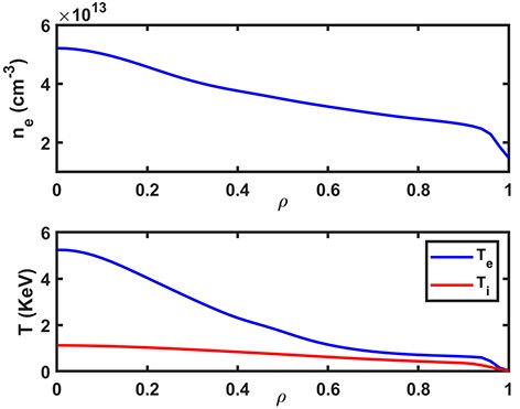
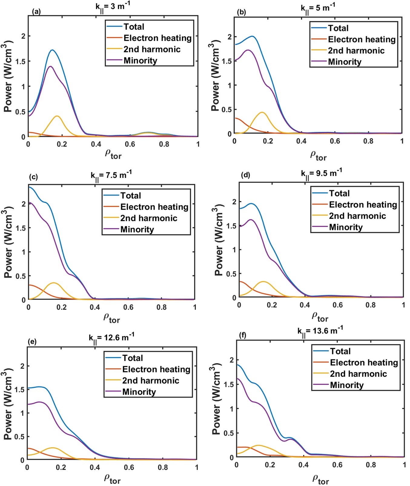
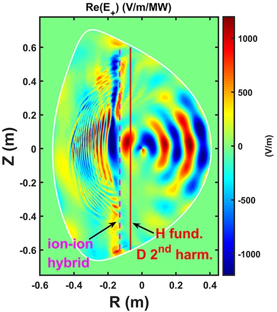
The antenna power absorption is further evaluated using TRANSP code package, which includes the TORIC [29]. The plasma profile, electron and ion temperature at the input are shown in figure 4. The central toroidal magnetic field is 2.4 T, and the hydrogen concentration is 5%. Heating by H+ minority fundamental, D+ majority second resonance and electron absorption is considered. The power absorption with k// of 3 m−1, 5 m−1, 7.5 m−1, 9.5 m−1, 12.6 m−1, 13.6 m−1 is simulated and shown in figure 5. In either case, the main power deposited position is in the range of ρ < 0.3, and the power absorption is mainly by minority ion. The position of maximum power absorption with k// of 7.5 m−1 and 13.6 m−1 is in the core (figures 4(c) and (f)). The simulation results indicate that antenna of k// = 7.5 m−1 is an appropriate value. The left-hand RF electric (E+) with k// of 7.5 m−1 is given in figure 6. In the case the RF wave can effectively propagate into the core and is absorbed.
Figure
4.
Plasma density and temperature profiles used for TORIC.
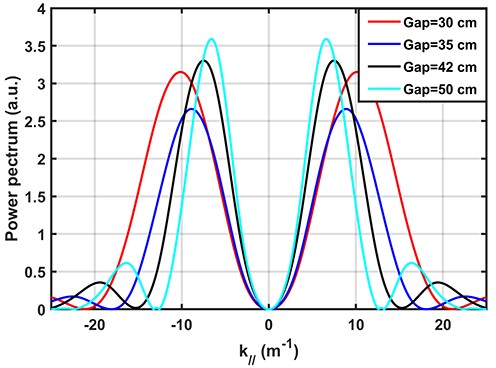
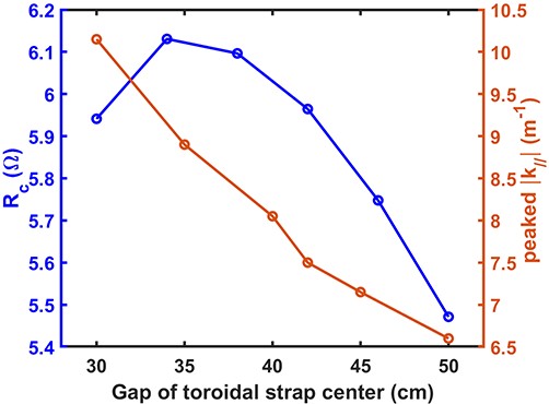
The FW coupling is related to the antenna spectrum and the distance of the FW cut-off layer and the antenna, expected as e−Ak//x. Moreover, the toroidal spectrum of the antenna mainly depends on the gap of the toroidal strap center, the antenna box shape, antenna frequencies and phasing. At the antenna frequency of 37 MHz and with a potential distance range of the strap center, the antenna power spectrum is depicted in figure 7, while the antenna coupling resistance is calculated using PML code, as shown in figure 8. The antenna phasing is set to dipole phase and the plasma profile used is the edge plasma of #101330 in figure 1. The antenna parameters are as follows: strap width is 15 cm, strap length is 77 cm, and distance between strap and last closed flux surface is 6 cm. The concentration of H is 10%. As the strap center gap increases, the peak values of the antenna’s toroidal spectrum decrease, but the optimal coupling for the antenna occurs when the strap center gap is 35 cm. The variation in antenna coupling does not exhibit the expected monotonic relationship with the spectrum and coupling changes. This is primarily because when the spacing between current straps is either too small or too large, the distance between the straps and the antenna box decreases. This results in an increase in the electric field at the antenna region. When the electric field exceeds a certain voltage threshold in the antenna region, the high electric field restricts the power of the antenna. Considering the influence of the antenna spectrum on wave absorption (as shown in figures 2 and 5), the antenna spectrum was designed with a gap of toroidal strap center of 42 cm and a value of 7.5 m−1.
Figure
7.
Antenna toroidal power spectrum with different gaps of toroidal strap center.
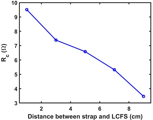
The antenna parameters including distance between straps and last closed flux surface (LCFS), strap length and strap width are optimized to improve antenna coupling. When evaluating the effect of the distance between the antenna and the LCFS on the antenna coupling, the parameters used in the simulation are as follows: strap width is 15 cm, strap length is 77 cm, strap center gap is 42 cm, and concentration of H is 10%. The antenna coupling resistance decreases rapidly with the increase of distance between the antenna and the LCFS. The fact that antennas need to be as close as possible to the plasma in order to enhance coupling is widely recognized. However, in practical ICRF antenna operation, this distance is also determined by the thermal load on antenna and the impurity sputtering of the antenna. In conventional experiments, the distance between the strap and the LCFS is 5–7 cm.
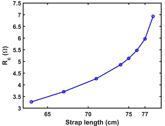
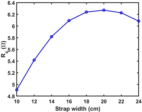
When optimizing the length and width of the antenna strap, the distance between the antenna and the LCFS is 6 cm, and the parameters selected are consistent with those used in figure 9. As the strap length increases, the antenna coupling resistance also increases as shown in figure 10. As for the width of the strap, in figure 11 it is shown that the optimal coupling of the antenna occurs when the current strap width is 20 cm. Similar to the relationship between antenna coupling and strap center gap, if the current strap is too close to the antenna box, it can limit the antenna’s coupling performance. The chosen current strap width for the antenna is 15 cm, taking into account mechanical support considerations. In future antenna optimizations, there are plans to increase the antenna width while enlarging the hole to reduce antenna weight.
Figure
9.
Relationship between antenna coupling and the distance of the strap to LCFS.
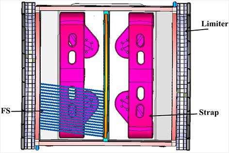
Based on the above analysis, the optimized antenna parameters are the current strap center gap of 42 cm, the strap length of 77 cm, and the strap width of 15 cm. The optimized antenna model, as shown in figure 12, includes current straps, Faraday screens (partially displayed), a box, and limiters. The tilt angle of the Faraday screens is approximately 7 degrees, which is consistent with the tilt angle of the magnetic field.
Figure
12.
Antenna model including current straps, Faraday screens (FS, partially displayed), a box, and limiters.
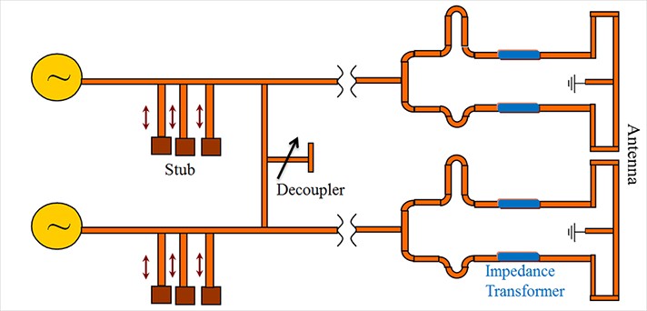
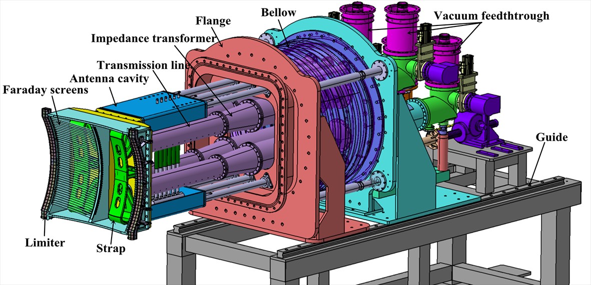
The antennas originally present in the I- and B-ports have been removed, and new antennas with a similar structure have been installed in the N- and I-ports on EAST. Figure 13 shows the distribution of the ICRF system with the newly installed antennas, while figure 14 displays the 3D structure of the new antenna. The Faraday screens and the current straps at the front of the antenna are suspended within the vacuum chamber. To reduce stress on the coaxial line, additional antenna cavity has been incorporated to enhance the mechanical strength, ensuring the integration of the antenna front with the rear flange as a unified structure. The RF power is supplied to the strap through both the top and bottom points, and the strap is grounded at the middle point. The poloidal 2 straps are powered by a transmitter with a source power of 1.2 MW and are connected by a T-conjunction. The distances between two poloidal straps and the T-conjunction are (0.7–0.75)λ and (1.2–1.25)λ, respectively, where λ represents the wavelength at 37 MHz. This scheme provides the poloidal straps with a 180-degree phase difference. The antenna operates at a frequency of 37 MHz, which is used for fundamental harmonic H minority heating. The entire antenna module can be moved in and out up to 70 mm along the radial direction. The main differences between the new and original antennas are as follows: (1) the antenna spectrum is optimized by adjusting the strap separation to 420 mm, (2) the Faraday screens (FS), straps, and limiters are fabricated with curved surfaces, and (3) a tapered impedance transformer with a length of 340 mm and a T-conjunction are utilized in the transmission line. The optimization of the antenna spectrum has enhanced the antenna’s load impedance. Simultaneously, changes in the radiofrequency topology of the antenna have reduced power reflections between the T-conjunction and the matching network. The combined effect of these two factors has resulted in a reduction in the maximum voltage and an increase in the input impedance of the system. For the RF circuits, once the input impedance reaches a certain level, changes in the load impedance do not significantly affect the system’s reflection coefficient [30]. The aforementioned improvements have, to a certain extent, alleviated the challenges posed to the system fluctuations by ELM.
Figure
13.
Integrated ICRF system with new antennas.
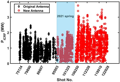
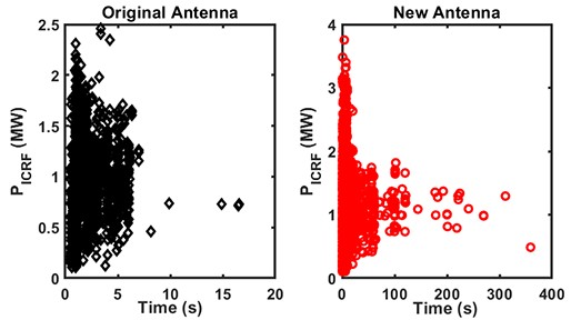
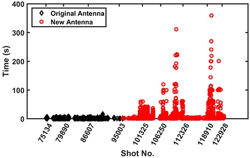
One unit of new antennas (N-port) is put into operation in spring 2021, while the other unit (I-port) also is put into operation in 2022. Figure 15 shows the output power of the new and original antennas. It can be seen that the output power level of a single new antenna is comparable to that of the original two antennas. When both new antennas are in operation, the power level is significantly higher, with a maximum output power exceeding 3.5 MW (3.8 MW/2.2 s). The pulse widths of the new and original antennas, as shown in figure 16, demonstrate that the new antennas perform better in long-pulse operation, with a maximum pulse length of 360 s. Figure 17 compares the output power of the new and original antennas over time. It is apparent that the original antennas mainly operate at pulse lengths below 8 s, while the new antennas can operate in the range of tens of seconds. The output power of the new antennas reduces during long-pulse operation due to high power RF wave causing excessive temperature in the ICRF antenna area, which necessitates lowering the antenna power. However, with the increase in antenna power, the thermal load on the antenna surface and previous limiter becomes a primary limiting factor for further power enhancement. This becomes a focal point for the next phase of antenna optimization.
Figure
15.
ICRF antenna power statistics over the past seven years on EAST.
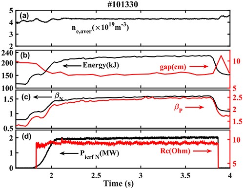
In terms of high-power performance of the new antenna, the N-port antenna power can reach up to 2.1 MW, and the plasma parameters for shot #101330 are presented in figure 18. The experimental parameters are as follows: plasma current Ip = 400 kA, toroidal magnetic field B0 = 2.5 T, plasma line averaged density ˉne = 4.3×10¹⁹ m−3, the gap between the antenna and LCFS is approximately 7.5 cm, lower hybrid wave (LHW) power is 2.8 MW and electron cyclotron heating (ECH) power is 1.5 MW. As shown in figure 18, when the ICRF power is injected, plasma stored energy is increased by 70 kJ (from 155 kJ to 225 kJ), the normalized toroidal βN is increased by 73% (from 0.95 to 1.65) and the poloidal βP is increased by 49% (from 1.68 to 2.5). The new antenna coupling resistance is approximately 9 Ω and steady at H-mode. It is noted that the H-mode discharge has the features of a small edge localized modes (ELM) and high poloidal βP, and this type of discharge has a high separatrix density and small-amplitude ELM [31].
Figure
18.
Plasma parameters for #101330: (a) plasma line averaged density, (b) plasma stored energy, and the gap between antenna and LCFS, (c) normalized toroidal βN and poloidal βP, (d) N-port antenna coupling power and resistance.
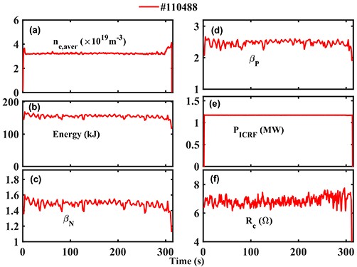
For a typical long-pulse discharge of #110488, steady-state high performance plasma of 313.2 s with ICRF heating is achieved, as shown in figure 19. The experimental parameters are as follows: Ip = 300 kA, B0 = 2.5 T, ˉne = 3.3×10¹⁹ m−3, the gap between antenna limiter and LCFS is approximately 6.3 cm, ICRF power is 1.2 MW, LHW power is 1.5–2 MW and ECH power is 1.6 MW. The antenna operates from 2 s to 313 s, with H-mode plasma the toroidal βN is 1.5 and the poloidal βP is 2.5. The antenna coupling resistance is 6‒7.5 Ω, and experimental results indicate that the ICRF antenna can operate for long-pulse discharge in a highly coupled state.
The newly designed two ICRF antennas have successfully operated on EAST. By balancing the absorption and coupling of RF waves, the antenna spectrum has been optimized. The maximum value of the antenna’s toroidal spectrum is 7.5 m−1. The experiment proved that the coupling of the antenna has been significantly improved, resulting in an increase of antenna power and pulse width on EAST. The achieved heating power and heating efficiency are currently the best of the device, enabling the device to operate in the megawatt level at the minute scale. These results demonstrate the reliability of this antenna physical design and provide a reference for future ICRF antenna design for CFETR.
Acknowledgments
This work was supported by the National Key Research and Development Program of China (Nos. 2019YFE03070000 and 2019YFE03070003); National Natural Science Foundation of China (Nos. 11975265 and 11775258); Comprehensive Research Facility for Fusion Technology Program of China (No. 2018-000052-73-01-001228); the Open Fund of Magnetic Confinement Fusion Laboratory of Anhui Province (No. 2021AMF01001); Hefei Science Center, CAS (No. 2021HSC-KPRD001).
Yuqing YANG (杨宇晴), Xinjun ZHANG (张新军), Yanping ZHAO (赵燕平), Chengming QIN (秦成明), Yan CHENG (程艳), Yuzhou MAO (毛玉周), Hua YANG (杨桦), Jianhua WANG (王健华), Shuai YUAN (袁帅), Lei WANG (王磊), Songqing JU (琚松青), Gen CHEN (陈根), Xu DENG, (邓旭), Kai ZHANG (张开), Baonian WAN (万宝年), Jiangang LI (李建刚), Yuntao SONG (宋云涛), Xianzu GONG (龚先祖), Jinping QIAN (钱金平), Tao ZHANG (张涛). Recent ICRF coupling experiments on EAST[J]. Plasma Science and Technology, 2018, 20(4): 45102-045102. DOI: 10.1088/2058-6272/aaa599
Liu, Z., Zhang, J., Wu, K. et al. Interaction between the core and the edge for ion cyclotron resonance heating based on artificial absorption plasma model. Plasma Science and Technology, 2024, 26(10): 105103.
DOI:10.1088/2058-6272/ad60f5

 DownLoad: