Yizhuohang LIU, Pingwei ZHENG, Xueyu GONG, Lan YIN, Xiaochang CHEN, Yijun ZHONG, Wenjun YANG. Numerical study of plasmas start-up by electron cyclotron waves in NCST spherical tokamak and CN-H1 stellarator[J]. Plasma Science and Technology, 2024, 26(7): 075101. DOI: 10.1088/2058-6272/ad2f3b
Citation:
Yizhuohang LIU, Pingwei ZHENG, Xueyu GONG, Lan YIN, Xiaochang CHEN, Yijun ZHONG, Wenjun YANG. Numerical study of plasmas start-up by electron cyclotron waves in NCST spherical tokamak and CN-H1 stellarator[J]. Plasma Science and Technology, 2024, 26(7): 075101. DOI: 10.1088/2058-6272/ad2f3b
Yizhuohang LIU, Pingwei ZHENG, Xueyu GONG, Lan YIN, Xiaochang CHEN, Yijun ZHONG, Wenjun YANG. Numerical study of plasmas start-up by electron cyclotron waves in NCST spherical tokamak and CN-H1 stellarator[J]. Plasma Science and Technology, 2024, 26(7): 075101. DOI: 10.1088/2058-6272/ad2f3b
Citation:
Yizhuohang LIU, Pingwei ZHENG, Xueyu GONG, Lan YIN, Xiaochang CHEN, Yijun ZHONG, Wenjun YANG. Numerical study of plasmas start-up by electron cyclotron waves in NCST spherical tokamak and CN-H1 stellarator[J]. Plasma Science and Technology, 2024, 26(7): 075101. DOI: 10.1088/2058-6272/ad2f3b
According to the physics of tokamak start-up, this study constructs a zero-dimensional (0D) model applicable to electron cyclotron (EC) wave assisted start-up in NCST spherical torus (spherical tokamak) and CN-H1 stellarators. Using the constructed 0D model, the results obtained in this study under the same conditions are compared and validated against reference results for pure hydrogen plasma start-up in tokamak. The results are in good agreement, especially regarding electron temperature, ion temperature and plasma current. In the presence of finite Ohmic electric field in the spherical tokamak, a study on the EC wave assisted start-up of the NCST plasma at frequency of 28 GHz is conducted. The impact of the vertical magnetic field Bv on EC wave assisted start-up, the relationship between EC wave injection power Pinj, Ohmic electric field E, and initial hydrogen atom density nH0 are explored separately. It is found that under conditions of Ohmic electric field lower than ITER (~ 0.3 V m−1), EC wave can expand the operational space to achieve better plasma parameters. Simulating the process of 28 GHz EC wave start-up in the CN-H1 stellarator plasma, the plasma current in the zero-dimensional model is replaced with the current in the poloidal coil of the stellarator. Plasma start-up can be successfully achieved at injection powers in the hundreds of kilowatts range, resulting in electron densities on the order of 1017–1018 m–3.
Traditional tokamaks rely on the volt-seconds generated by the central solenoid (CS) to heat the plasma and start-up, a process known as Ohmic start-up. However, in reactor-scale tokamak devices such as the International Thermonuclear Experimental Reactor (ITER), the CS cannot provide a sufficient number of volt-seconds, resulting in an Ohmic field [1] as low as 0.3 V m–1, significantly lower than the values on current tokamak devices (~ 1 V m–1). Spherical tokamaks (ST) are a special type of tokamak device with a small aspect ratio, and some STs lack the CS and cannot rely on Ohmic induction to start-up the plasma. Even if they have a CS, the limited internal space results in a smaller Ohmic electric field (E) compared to traditional tokamak devices like JET (1 V m–1). Therefore, both reactor-scale tokamaks and STs face difficulties in achieving pure Ohmic start-up and require auxiliary start-up methods.
If there is no CS, plasma start-up completely relies on auxiliary methods [2]. Radio frequency wave assisted start-up is one of these methods, such as using electron cyclotron (EC) waves to start-up the plasma on STs like CDX-U [3] and QUEST [4], or employing mode-converted electron Bernstein wave (EBW) to start-up plasma on MAST [5]. In addition to these methods, there is start-up using coaxial helicity injection on HIT-II [6] and merging compression relies on the use of induction on MAST [7].
If the CS exists but the Ohmic field is limited, auxiliary methods are still needed to start-up the plasma. EC wave is one of the important methods for this purpose because EC wave can significantly reduce the required Ohmic field for start-up, making electron cyclotron resonance heating (ECRH) for plasma current start-up particularly relevant. For example, EC wave assisted start-up has been utilized on the DⅢ-D [8] device, as well as on TST-2 [9] and LATE [10] devices. EC wave assisted start-up has been extensively studied through numerous experiments [11‒17] and is considered a mature and reliable start-up method.
Tokamak start-up primarily involves heating neutral gas to generate plasma and produce plasma current. The start-up process is divided into three stages: plasma breakdown, plasma burn-through, and plasma current ramp-up. Many tokamak start-up experiments fail during the burn-through, and zero-dimensional (0D) models of start-up can help understand the key physics during burn-through to reduce start-up failures. Additionally, both STs and large devices like ITER have operational space limitations due to engineering constraints, necessitating predictable simulations for plasma start-up.
The 0D model treats the plasma as a uniformly distributed entity, and it can provide information reflecting the evolution of key physical quantities during start-up. The use of a 0D model to simulate tokamak Ohmic start-up has shown good agreement with experimental results, demonstrating its reliability. Therefore, the 0D model can be utilized to predict the start-up process of STs and stellarator devices. According to the work of Lloyd etal [18], Kim [19], and others who have established 0D models for tokamak start-up, this work combines the characteristics of STs and stellarators, establishes a new model, autonomously develops program code, and conducts comparative validation. Start-up simulation researches are carried out based on the parameters of the target devices. However, there has no universal model for non-inductive plasma current ramp-up during pure RF heating process, and construction of a plasma current ramp-up model without a CS is a challenge. It is necessary to consider factors such as the contribution of high-energy electrons during RF heating to the plasma current [17, 20, 21], current jump phenomena [15] etc. Hence, this study only focuses on the Ohmic current ramp-up model in the presence of a limited CS. The construction of plasma current ramp-up model during RF heating process will be carried out in our future work.
First, a comparison with literature results is performed to validate the reliability of the program in this study. The 0D model is then extended to a model for EC wave assisted start-up in STs under finite electric fields. Then under the conditions of 28 GHz EC wave assisted start-up, the effects of the vertical magnetic field Bv are studied, as well as the relationship between the electron cyclotron wave injection power Pinj and the Ohmic field E, and the relationship between Pinj and the neutral atom density nH0. Compared to tokamaks and STs, stellarators do not have a plasma current, which necessitates modifications to the 0D model. Replacing the traditional Ohmic power requires for start-up with electron cyclotron heating (ECH) power. The poloidal coils on the stellarator device generate poloidal magnetic fields, which, in essence, is similar to how plasma current in tokamaks and STs produces poloidal magnetic fields. The current in the poloidal coils of the stellarator device replaces the plasma current generated by the Ohmic field in the 0D model, thereby extending the 0D model into a pure EC wave start-up model for stellarators.
This paper is divided into five sections. After introducing the research background and motivation in the text, section 2 constructs a physical model applicable to EC wave (assisted) start-up for STs and stellarators based on a 0D tokamak model. Section 3 validates the correctness of the model presented in this paper. Section 4 presents simulation results for EC wave assisted start-up on the NCST spherical tokamak and pure EC wave start-up on the CN-H1 stellarator. Section 5 provides a summary and conclusions.
2.
Theoretical model for EC wave (assisted) start-up simulation
The 0D codes for tokamak plasma start-up primarily include DYON [19], SCENPLINT [22, 23], and BKD0 [24, 25]. Kim built a new tokamak start-up model based on Lloyd’s 0D theoretical model [18], which is suitable for both pure Ohmic start-up and EC wave assisted start-up under finite electric fields. This new model, based on Kim’s work, simulates the start-up results of the JET device and closely matches experimental results [26]. Using Kim’s new model as a foundation, this work establishes a 0D physical model for EC wave start-up in STs and stellarators. The theoretical model mainly comprises equations for electron and ion energy balance, density balance for particles (electrons, ions, and neutral atoms), and a current model to generate poloidal magnetic fields.
2.1
Energy balance equations
Assuming that the plasma has a uniform distribution of density and temperature, and that all heating power is absorbed by electrons, the electron energy balance equation is as follows:
32d(neTe)dt=Poh+Paux−(Piz+Prad)−Pequi−Peconv,
(1)
dTedt=2Pe3ne−Tenednedt,
(2)
where Poh and Paux represent Ohmic heating and auxiliary heating, electron loss power consists of collisional ionization power loss Piz, radiation power loss Prad, equilibration power loss Pequi and convective transport power loss Peconv. Each power term is normalized by the plasma volume. In equation (2), the first term on the right-hand side, Pe represents the total electron power, which is the sum of all these power terms.
This study assumes that the CS is installed in the spherical torus, but the provided Ohmic electric field is limited, and the Ohmic power is insufficient. In the stellarator, which lacks a central helical coil, Ohmic power is not considered. The Ohmic heating power per unit volume is given by:
Poh=I2pRpVp.
(3)
For ionization collision loss power, the kinetic energy lost by a free electron is equivalent to the potential energy of a bound electron within an atom. Therefore, the ionization loss power is given by:
where Wz+→(z+1)+A is the ionization energy required to ionize an atom or an ion from z+ to (z+1)+ charge state. nz+A represents an ion of species A of which the ionic charge is z. <σv>0→1+A,iz is ionization rate coefficient, its superscript indicates the change of the ion charge in the atomic reaction, the subscripts represent the species of the kind of the reaction. For example, <σv>z+→(z−1)+RB indicates a power coefficient for recombination and bremsstrahlung radiation and <σv>z+line indicates a power coefficient for line radiation. The rate coefficients and power coefficients used in the simulation are obtained from Atomic Data and Analysis Structure (ADAS) package [27]. In this study, hydrogen related reaction rate coefficients and power coefficients are selected. VAn represents the neutral volume of species A within a plasma volume [19], Vp represents plasma volume. The total electron power loss through radiation is
where <σv>z+→(z−1)+rec represents the recombination rate coefficient. When Te > Ti , electrons lose energy through elastic coulomb collisions with ions, i.e. the equilibration process, it is well known as
where MA is the ion mass in amu, z is charge state, lnΛ is the Coulomb logarithm, lnΛ = 10. When electrons are transported out of a plasma, electrons themselves possess kinetic energy, leading to electron energy loss. The transport power loss as
Peconv=32neTeτe.
(7)
In the model, it is assumed [19] that the electron confinement time τe is equal to the ion confinement time (τe = τA). The confinement time includes two parts: parallel transport and perpendicular transport. As the burn-through progresses, magnetic field transition from open to closed configurations. For the open magnetic field configuration, the parallel transport assumed as a transonic ambipolar flow along a magnetic field line towards the vessel wall [19]. Parallel transport is related to the effective connection length Lf and the particle velocity Cs, i.e. τ∥=LfCs, where the effective connection length is defined as: ensuring that electrons undergo sufficient collisions with atoms, the average free path of electrons along magnetic field lines. It is calculated as Lf=0.75×aBϕBvexp(IpIref), where Bϕ and Bv are the toroidal field and the stray field, Iref indicated the reference current when the magnetic field transition happens. The ion sound speed is Cs=√Te+TimA. For perpendicular transport, the model assumes that the perpendicular transport component follows the Bohm diffusion model [19], i.e. τ⊥=a(t)VBohm(t), where a is minor radius, VBohm(t)=2DBohm(t)a(t), DBohm(t)=116Te(t)[eV]Bϕ. So, the confinement time is 1τ=1τ⊥+1τ∥.
Ions are assumed to be heated only by Pequi and lose energy through charge exchange reaction and ion convective transport. The ion energy balance equation is
32d(niTi)dt=Pequi−Pcx−Piconv,
(8)
dTidt=23Pini−Tinidnidt,
(9)
where the ion density ni and ion temperature are defined to be ni=n1+A+∑I∑z⩾1nz+I, Ti=T1+A=Tz+I, where n1+A and nz+I are gas ion density and impurity ion density with charge stage z+. T1+A and Tz+I are gas ion temperature and impurity ion temperature, Pi represents the total ion power.
The energy of charge exchange loss is equal to the energy difference between high energy ions and neutral particles (T0 = 0.026 eV). The model assumes that neutral gas atoms are the sole source of electrons in charge exchange and correspondingly, gas ions are the only particles capable of capturing free electrons, thus the reaction occurs only in VAn,
Pcx=VAnVp(32n0A(Ti−T0)∑A<σv>1+→0A,cxn1+A).
(10)
As in equation (7), the ion convective transport loss is calculated as
Piconv=∑A∑z⩾132nz+ATiτA,
(11)
where τA is the ion confinement time.
2.2
Particle balance equations
Assuming that the gas molecules are dissociated, the number of atoms decreases due to ionization and charge exchange, leading to an increase in recombination reaction and atomic injection flux.
where the last term on the right side of the equation is the total influx of neutral atoms ΓtotalA,in=VpYAAn1+AτA, γAn=1−Vp−VAnVv is a neutral volume coefficient. γAnVv is the total neutral volume within the plasma volume [19]. YAA is the rate of particles transported out of the plasma and interacting with the wall through sputtering or cycling [19] (wall recycling coefficient), with the subscript indicating the incident ion and the superscript indicating the sputtered or recycling particles. Kim proposed that [19] particles in the plasma collide with the wall, leading to reactions where ions exchange charges with the atoms in the wall, resulting in the generation of new atoms and ions, thereby affecting particle balance. The recycling coefficient [19] is defined as the fraction of the particle influx to the particle outflux. When the residual neutral atoms from the previous discharge in the container saturate the container walls, the recycling coefficient is greater than 1; conversely, it is less than 1. Therefore, in this paper during the start-up process, the coefficient fluctuates around 1.
Regarding the volume of neutral atoms in a plasma, due to the neutral shielding effect [19], as atoms ionize continuously, the electron temperature and density increase. The average free path for atomic ionization decreases, which prevents neutral atoms from outside the plasma from entering the plasma, effectively reducing the volume of neutral atoms within the plasma VAn,
VAn={2πR(πka2−πk(a−λA,iz)2),λA,iz<aVp,λA,iz⩾a,
(13)
where λA,iz is the mean free path for ionization (λA,iz = vA/<σv>iz, vA is the atom sound speed) , k is the elongation, R and a are major radius and minor radius.
The ion particle balance includes ionization, charge exchange, and recombination reactions. The equation is given by:
According to the charge neutrality of the plasma, the electron density is ne=∑A∑z⩾1znz+A.
2.3
Electron cyclotron resonance heating model
In this paper, the auxiliary power Paux in the electron energy balance is denoted as PECH, and the ECH heating power [28] is
PECH=Pinj(1−foe−ηpol,o−fxe−ηpol,x)Vp,
(15)
where Pinj is the incident EC wave power, ηpol,o and ηpol,x are the dimensionless optical depths for the ordinary mode (O mode) and the extraordinary mode (X mode), respectively. fo and fx are the fraction powers for the O mode and the X mode, respectively. For the harmonic number N = 1, the optical depths for the modes of fundamental harmonic heating of the EC wave are given by [28]
ηO=π2R0λTe[eV]mec2nenc√1−α[1+n2||(0.5−α)]−1,
(16)
ηX=π2R0λTe[eV]mec2n2||(2−α)3/2(1+α)2α−1,
(17)
where λ is the free-space wavelength of the EC wave, α is ne/nc, nc = meε0ω2/e2 is the cut-off density where the EC wave frequency equals the plasma frequency, n||= cos(π/2–ϕ) is the parallel component of the refractive index, e is the charge of an electron, ω is the incident wave angular frequency, me is the electron mass, c is the speed of light, ε0 is the vacuum permittivity, ϕ is the toroidal angle between the direction of electron cyclotron wave incidence and the radial direction. The radial direction is perpendicular to the toroidal magnetic field direction on the resonance layer. Therefore, the angle between the EC beam and the toroidal magnetic field on the resonance layer is (π/2–ϕ), R0 is the major radius.
For N⩾ 2 harmonic heating of an EC wave, the optical depths are calculated [28]:
Here n2⊥=−B±√B2−4AC2A is the perpendicular component of the refractive index, where A = S, B=−(S+P)(S−n2∥)+D2, C=P((S−n2∥)2−D2. The plus sign corresponds to the O mode and the minus sign to the X mode. S, P and D are the components of the dielectric tensor in the cold plasma dispersion relation, S=1−ω2peω2(ω2ω2−ω2ce)=1−α(N2N2−1), P=1−ω2peω2=1−α, D=ω2peω2(ωωceω2−ω2ce)=−α(N2N2−1).
2.4
Current model for generating poloidal magnetic field
For tokamaks and spherical torus, under the presence of the Ohmic electric field, the poloidal magnetic field is generated by the plasma current Ip. The corresponding equation is:
dIpdt=Vloop−IpRpLp,
(19)
where Vloop is the loop voltage, Ip is the plasma current, Rp=5×10⁻⁵×lnΛ×Zf×2Ra×T−32e[eV] is the electric resistance of a plasma, Lp=μR(ln8Ra−2+li2) is the self-inductance, li = 0.5 is a dimensionless normalized plasma inductance, Zf=∑A∑Znz+Az2∑A∑Znz+Az is an effective charge.
The plasma current generates a poloidal magnetic field in tokamaks and STs and produces a helical magnetic field with the toroidal magnetic field. For ST devices without the Ohmic electric field, the plasma current needs to be replaced through other means, such as during the process of electron cyclotron wave heating, this requires an additional current start-up model. While a stellarator does not have a plasma current, the poloidal magnetic field in a stellarator is generated by the current in the poloidal coils. Therefore, in theory, the current in the poloidal coils of a stellarator can substitute for the Ip in a tokamak. This study assumes that the current in the poloidal coils of the stellarator is a time-varying piecewise function, where t0 is the current ramp-up time in the poloidal coils, and I0 is the constant current during the flat-top phase. The specific model is as follows:
Ip={I0t0×t,t⩽t0I0,t>t0.
(20)
Here, Ip represents the current within the poloidal coils of the stellarator.
3.
Model validation
Kim used three 0D models for comparison to identify the reasons for differences in simulated results among various models [29]. Among these models, the numerical simulation results of DYON are in good agreement with the experimental results of Ohmic start-up in the JET device [26, 30]. Therefore, DYON was chosen for validation. In the first benchmark, DYON was simulated for Ohmic start-up of pure hydrogen plasma under the ITER parameters [29]. This study conducted a comparative validation using the conditions from the reference [29]. The simulation setting and input parameters are as follow: Ohmic burn-through, i.e. no ECH. Pure hydrogen, i.e. no impurities. The plasma volume is a constant value (R = 5.65 m, a = 1.6 m, κ = 2), vessel volume Vv = 1000 m3. The prefilled fuel gas pressure P0 = 0.8 mPa. Constant loop voltage Vloop = 12 V, toroidal magnetic field BT = 2.65 T (R = 6.2 m), vertical magnetic field Bv = 2 mT, Iref= 100 kA. Initial degree of ionization γ(0) = 0.2%, wall recycling coefficient YHH = 1, the remaining initial conditions are listed in table 1.
Table
1.
The initial conditions for the simulation.
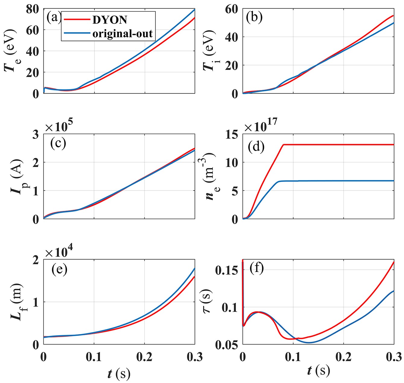
Figure 1 describes a comparison between the simulation results of the current study and the results obtained using the DYON model. The results show good agreement, particularly in plasma current in figure 1(c), and plasma temperature in figure 1(a). Figures 1(f) and (d) show that the constrained time τ and the electron density ne are of similar magnitude and exhibit a similar trend, but there are some differences. Possible reasons for differences in electron density in figure 1(d) include: differences in the interpolation of the rate coefficients and power coefficients from ADAS in numerical simulations; the effective connection length Lf as shown in figure 1(e) affects the confinement time in figure 1(f), and ultimately affects the electron confinement loss; and the recycling of atom causes the difference to gradually increase.
Figure
1.
The results of this model (in blue) and the results from DYON (in red) (a) Electron temperature, (b) ion temperature, (c) plasma current, (d) electron density, (e) effective connection length, (f) particle confinement time.
The above results validate the correctness of the 0D model presented in this article. The next step involves simulating the EC wave start-up process using the NCST at Nanchang University and the CN-H1 stellarator as the subjects of investigation.
4.
Simulation results
4.1
Results of 28 GHz EC wave assisted start-up of NCST under finite electric field
For the ST, this study only considers plasma start-up with EC wave assistance under finite electric field. In the absence of Ohmic field, the existing model cannot be used, and modifications to the plasma current ramp-up model in the 0D model will be needed. For example, reference to the plasma current ramp-up model during EC wave heating, as discussed in references [31, 32], will be considered in future work.
The spherical tokamak at Nanchang University (NCST) is the first device in China capable of achieving plasma current start-up through the merge compression method, and it is equipped with an electron cyclotron wave heating system. Major radius and minor radius are 0.4 m and 0.24 m, respectively. Toroidal magnetic field BT = 0.36 T, discharge time is 100 ms, elongation ratio k = 1.5–2.0. Assuming that spherical tokamak has a limited CS that can provide a very weak Ohmic electric field, similar to ITER (~ 0.3 V m−1), the process of plasma start-up for spherical tokamak assisted by EC waves under finite electric field is simulated based on this.
The simulation setting and input parameters are as follow: electron cyclotron wave assisted heating, wave frequency f = 28 GHz, the incident EC wave power Pinj = 5 kW, N = 2, 100% X mode, single-pass absorption, toroidal injection angle: 10°. Pure hydrogen plasma, plasma volume Vp = 0.91 m3, vessel volume Vv = 2.5 m3. Vertical magnetic field Bv = 1 mT. According to the X2 mode frequency, calculate the corresponding resonant magnetic field as B = 0.5 T (ω/ωce =2). Initial degree of ionization γ(0) = 0.2%. Wall recycling coefficient YHH = 1.01, initial plasma current Ip(0)=π×a2×e×γ0×4.8×1020×133.322×43×E [29]. According to the equation Iref=2π×a×Bv/μ0 in BKD0 [29], Iref = 1.2 kA. The initial conditions for the plasma are found in table 2. It is assumed that the X2 mode EC wave is injected into the plasma from the low-field side.
Table
2.
The initial conditions for the simulation.
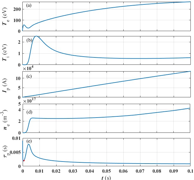
As atoms continue to ionize, the electron density increases. With heating from Ohmic and ECRH powers, both electron temperature and density rise. The increase in electron temperature and density leads to an escalation in ECRH power deposition. Furthermore, the rise in electron temperature lowers the plasma resistance, which results in an increase in plasma current and Ohmic power, further enhancing ionization. This forms a positive feedback effect. Figure 2 shows the simulation results of 28 GHz X2 EC wave assisted start-up of NCST spherical tokamak plasma, including the evolution of (a) electron temperature Te, (b) ion temperature Ti, (c) plasma current Ip, (d) electron density ne and (e) particle confine time τp over time. The red dot in figure 2(e) indicates that the magnetic structure is beginning to transform. The electron temperature rises to 268 eV, the plasma current reaches 136.6 kA, and the electron density reaches 4.25×10¹⁷ m−3. The magnitude of the electron density indicates significant neutral atom ionization, and the continued rise in plasma current demonstrates successful plasma start-up. Because the ion heating power Pequi is greatly affected by particle density, a significant increase in Ti requires a particle density of over 1017 m−3 and continuously increases over time. Although the electron density in figure 2(d) increases, the magnitude is limited to 1017 m−3, and the continuous increase in temperature leads to an increase in ion loss power Pcx, Piconv. Therefore, in figure 2(b), the ion temperature Ti shows a downward trend and finally stabilizes, with a final ion temperature of only 0.62 eV.
Figure
2.
Results of 28 GHz X2 mode EC wave assisted start-up on NCST. (a) Electron temperature, (b) ion temperature, (c) plasma current, (d) electron density, (e) particle confinement time. The red dot in plot (e) indicates that the magnetic structure is beginning to transform.
The experimental results on LATE [33, 34] and TST-2 [35] have shown that a stronger vertical magnetic field and higher ECH power are favorable for achieving higher plasma current during the start-up phase. This is particularly observed when the transition in magnetic field structure occurs, leading to a current jump [15]. Additionally, the plasma current during the maintenance phase is generally positively correlated with Bv. Investigating the effects of the Bv phenomenon during start-up is crucial for a deeper understanding of the fundamental physics involved in the ST start-up process. Whether it is pure Ohmic start-up in the tokamak plasma or electron cyclotron wave assisted start-up in the ST plasma, the parallel transport in the confinement time is significantly influenced by the vertical magnetic field, ultimately affecting particle balance. The presence of vertical magnetic field Bv is necessary during the plasma current start-up process. For open magnetic surfaces, vertical magnetic field affects the constraint of collision free electrons and the drift loss of the main plasma. For closed magnetic surfaces, vertical magnetic field is used to maintain plasma equilibrium and the suppression of the main plasma drift loss is the key to forming a closed magnetic surface. Therefore, the value of Bv has a substantial influence on the process of plasma start-up, making it necessary to study the effects of the Bv on plasma start-up.
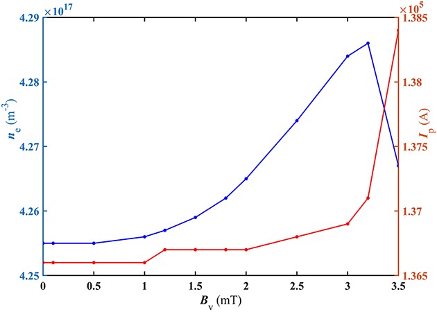
As the start-up progresses, the dominant mode of transport loss shifts from parallel transport to perpendicular transport. This transition is a result of a change in magnetic structure, moving from an open magnetic field line configuration to a closed magnetic field structure. Bv directly affects parallel transport, and its influence is particularly significant during the early stages of start-up. Under 28 GHz EC wave assisted start-up conditions, changes in the value of Bv produce the results shown in figure 3. As depicted by the orange curve in figure 3, the plasma current increases with the increase in magnetic field, which is consistent with the conclusion of the experiment. As depicted in figure 3, when the vertical magnetic field Bv is below 1.0 mT, the plasma current does not significantly vary with Bv. Upon reaching 1.2 mT, there is a slight increase in current. However, within the range of 1.2‒2.0 mT, no significant changes are observed. Beyond 2.0 mT, a substantial increase in current occurs and upon surpassing 3.0 mT, it experiences a pronounced escalation. It should be noted that for successful start-up, there exists an upper limit of Bv at 3.5 mT corresponding to the maximum achievable plasma current.
Figure
3.
Variation of electron density (the blue curve) and plasma current (the orange curve) with vertical magnetic field.
As shown by the blue curve in figure 3, under successful start-up conditions, the ne initially increases with Bv and then decreases. The reason for this variation in ne is as follows: as the confinement time partially decreases, more particles are lost, leading to an increase in the influx of circulating particles from the wall. This influx results in the increase in ne. However, when the value of Bv reaches 3.5 mT the ne is smaller compared to 3.2 mT, because the electron confinement loss is greater, even with the influx supplementation, the ne is actually smaller, and when Bv exceeds 3.5 mT, the decrease in constraint performance leads to plasma start-up failure. When Bv = 3.2 mT, the electron density reaches ne,max = 4.28×10¹⁷ m‒3. Even when Bv approaches 0, the plasma can still achieve successful start-up. According to the theoretical model of confinement time, as Bv tends to 0, τ||tends to infinity, meaning 1/τ ≈ 1/τ⊥. In this case, confinement time is only influenced by vertical transport, although in reality, this value is not exactly zero.
4.1.2
The relationship between Pinj and E
In a tokamak, the induced Ohmic power from the CS is an important heating factor. However, in STs, the Ohmic field is limited. Injecting EC waves can effectively reduce the required Ohmic field for start-up. For example, experiments have been conducted on the J-TEXT device to study the relationship between ECH power and Ohmic field (loop voltage) [36]. The experiments observed changes in E with respect to PECH and determined the minimum power required for start-up.
Due to the positive feedback effect of PECH, to ensure a successful start-up, it is necessary to determine the minimum injected EC wave power required for successful start-up at different Ohmic field levels. Alternatively, it is necessary to determine the minimum Ohmic field required for a given EC wave power. With the same initial conditions as shown in figure 2, the relationship between the EC wave injection power (Pinj) and the electric field (E) is obtained, as shown in figure 4.
Figure
4.
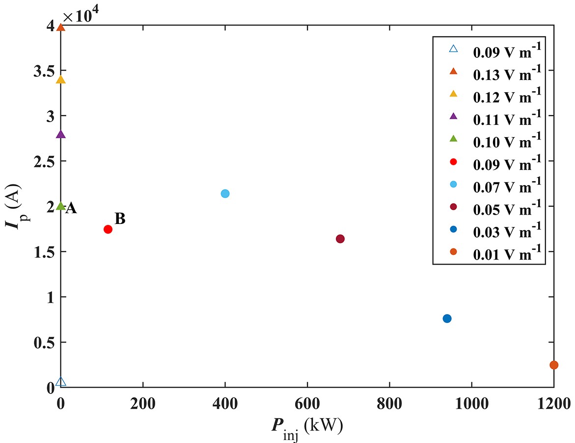
The influence of injected power (Pinj) on electric field (E) during start-up. The triangle represents start-up without EC wave. Different colors represent different electric field values. Solid triangles and circles indicate successful start-up, while hollow triangle indicates failure.
In figure 4, the triangle represents start-up without EC wave (i.e. pure Ohmic start-up), point A represents the minimum electric field (Emin = 0.10 V m−1) required for a successful pure Ohmic start-up. If the Ohmic field is lower than this value, start-up fails, and the plasma current does not exceed 19.9 kA. For instance, when the electric field is 0.09 V m−1, start-up fails, and the current decreases significantly to only 0.55 kA. It was found that changes in the electric field greatly affect the plasma current, even if the injection of EC waves does not significantly increase the plasma current. This is because the plasma current is directly affected by the electric field, while the injected EC power mainly affects the electron temperature and does not directly affect the plasma current. When the electric field decreases, the injection power required for start-up increases, but the plasma current does not necessarily increase. Even if the injected EC power increases significantly, the increase of the plasma current is not significant. The graph shows that the injection of EC waves can lower the required Ohmic field for start-up, consistent with the research results on J-TEXT. Point B represents that injecting EC wave power of Pinj = 115 kW at an Ohmic field of 0.09 V m−1 ensures a successful start-up, but below this power level, start-up fails. When Pinj = 1.2 MW, the electric field can be reduced to 0.01 V m−1. This indicates that as the EC wave power increases, the required Ohmic field for a successful start-up decrease.
4.1.3
The relationship between Pinj and nH0
To minimize the loop voltage and reduce hardware requirements in a tokamak, the vessel pressure is set near the minimum value on the Paschen curve [37]. The pressure affects electron avalanche. If the pressure is too high, the electron energy is insufficient to ionize atoms. If the pressure is too low, the atomic density is insufficient to provide enough electrons. The impact of pressure on the breakdown phase is well understood, and a 0D model can further explore the influence of EC wave injection on pressure during start-up. Under the conditions of the EC wave frequency corresponding to the cutoff density, the 0D model can obtain the initial atomic density nH0 and electron density ne for successful start-up at different injection powers Pinj. According to the equation between pressure and initial atomic density (table 1), the effect of injection power Pinj on pressure p can be determined. The relationship between Pinj and nH0 is studied under 28 GHz conditions. Additionally, the study on the relationship between the electric field and injection power indicates that the Ohmic field has a significant impact on start-up. Therefore, further research is conducted under three different electric field conditions (0.30 V m−1, 0.20 V m−1, 0.10 V m−1).
As shown in figure 5, nH0 increases with E and Pinj, indicating that the maximum pressure for start-up increases with the injection power of EC waves. In comparison to the changes in initial atomic density caused by injection power, the changes in initial atomic density caused by the electric field are even greater. Secondly, at the order of atomic density around 1017 m−3, the variation in atomic density caused by changes in injection power is small. For example, the maximum initial atomic density between the first two points (5 kW and 50 kW) does not differ significantly. Although the injection power changes are the same, there are differences in atomic density changes under different electric fields. For instance, at 0.1 V m−1, with the injection power changing from 5 kW to 1 MW, the atomic density increases from 1×10¹⁷ m−3 to 2×10¹⁷ m−3. At 0.3 V m−1, the atomic density increases from 3.2×10¹⁷ m−3 to 4.6×10¹⁷ m−3. The change in atomic density is greater under the condition of 0.3 V m−1. Finally, according to the relationship between pressure and initial atomic density, at E = 0.1 V m−1, the maximum pressure for start-up increases from 0.20 mPa to 0.41 mPa. At E = 0.2 V m−1, the maximum pressure for start-up increases from 0.43 mPa to 0.68 mPa. At E = 0.3 V m−1, the maximum pressure for start-up increases from 0.66 mPa to 0.95 mPa. This indicates that EC wave injection expands the pressure range for successful start-up, and a larger pressure range is achieved under higher electric fields.
Figure
5.
The relationship between the injection power Pinj and the maximum initial atomic hydrogen density nH0.
The preceding study examined the impact of EC wave injection on plasma start-up under finite Ohmic fields. The graph depicting the relationship between Pinj and E demonstrates that an increase in Pinj leads to a continuous reduction in the required electric field for start-up. Therefore, theoretically, even in the absence of Ohmic fields, pure EC wave start-up for stellarators is feasible as long as Pinj is sufficient.
A stellarator is an experimental device equipped with helical winding coils to magnetically confine high-temperature plasma, ensuring its stable and safe operation. It emulates nuclear fusion reactions that occur in the core of stars, aiming to generate continuous energy and is currently one of the most promising candidates for achieving controlled and clean nuclear fusion energy. The precursor of CN-H1 stellarator was the H-1NF at the Australian National University. In a collaborative project between University of South China and the Australian National University, H-1NF was introduced as the first stellarator in China. For detailed information on the device, please refer to the reference [38]. The main parameters [39] of CN-H1 are listed in table 3.
The following is a simulated CN-H1 stellarator with 28 GHz EC wave start-up. The initial conditions for the start-up simulation are as follow: electron cyclotron wave heating, 100% X mode, N = 2, single-pass absorption. Vp = 1 m3, Vv = 32 m3. Pure hydrogen plasma. The flap-top current within the poloidal coils I0 = 180 kA, the current ramp-up time t0 = 50 ms. The remaining initial conditions are listed in table 4.
Table
4.
The initial conditions for the simulation.
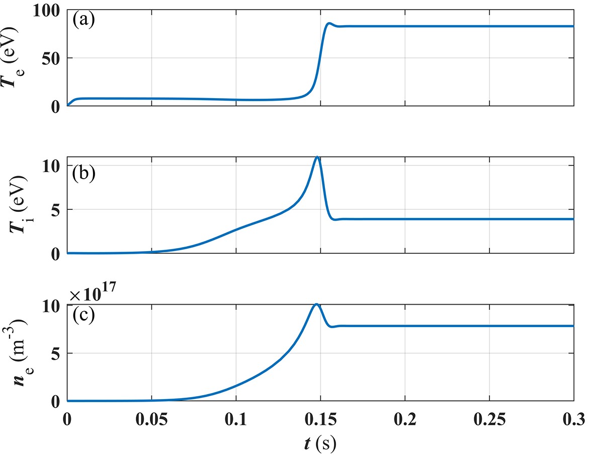
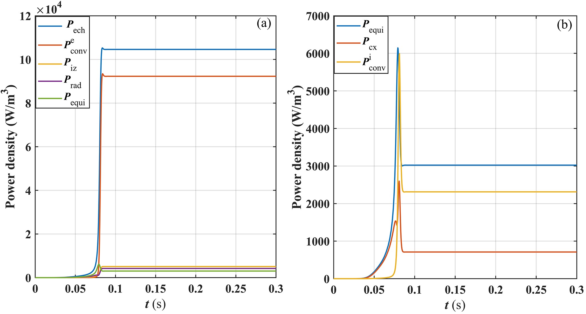
The simulation results for CN-H1 are shown in figure 6, where the electron temperature reaches 82.7 eV, and the electron density reaches the order of 1017 m−3, reaching a flat-top within 0.16 s. The electron energy balance and ion energy balance are shown in figure 7. In the electron energy balance, the dominant power loss is electron transport power Peconv before the rapid rise of PECH, with the equilibrium power Pequi playing a dominant role in electron power loss. In the ion energy balance, the primary power loss is ion transport power Piconv, with charge exchange power Pcx being the primary power loss before the rapid increase in equilibrium power. EC wave injection can expand the operational space to achieve better plasma parameters. By changing the simulation conditions with injection power Pinj = 400 kW and initial atomic density nH(0) = 1×10¹⁷ m−3, the simulation results are shown in figures 8 and 9.
Figure
6.
Simulation results for CN-H1 electron cyclotron wave start-up under the conditions of Pinj = 200 kW. (a) Electron temperature, (b) ion temperature, (c) electron density.
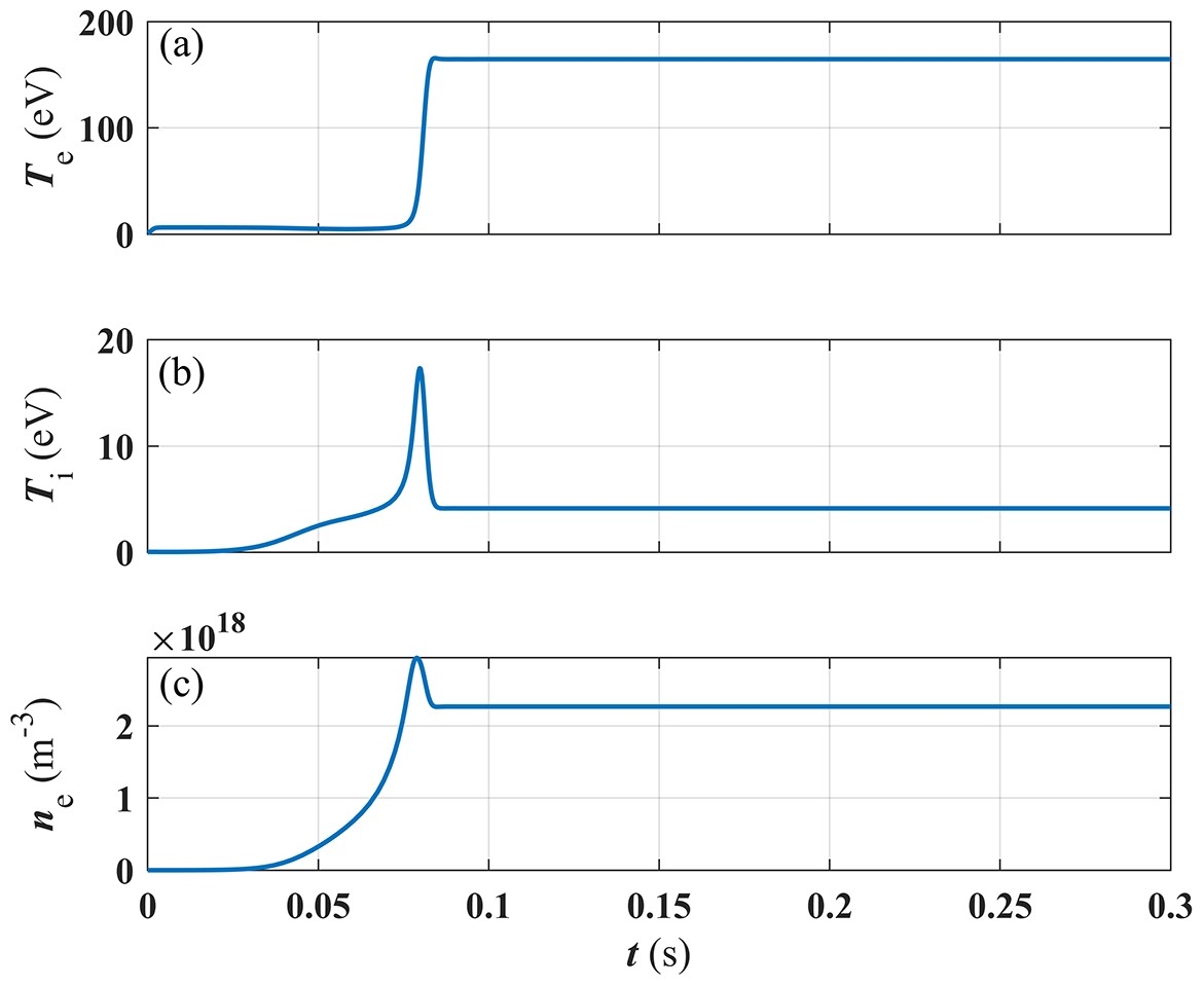
Figure 8 presents the simulation results of the CN-H1 with EC wave injection power of 400 kW. In this case, the electron temperature reaches 164.8 eV, the ion temperature reaches 4.12 eV and the electron density reaches 2.26×10¹⁸ m−3. By the time 0.09 s is reached, both the electron density and electron temperature have reached the flat-top. The plasma start-up process in figure 8 has phenomenon that in the initial stage, both temperature and density increase over time, reach a peak, and then decrease. This is because after the electron density reaches a peak, the temperature begins to increase significantly. The increase in temperature lead to increase in the loss of ions transport to the wall and the reaction rate of recombination, but ionization has been basically completed, resulting in a decrease in electron density after the peak electron density is reached. Until these reactions reach equilibrium, the electron density stops decreasing. The ion temperature varies with changes in electron density, and due to the magnitude of the electron density, even a slight change result in a significant change in ion temperature. Figure 9 shows the energy balance at Pinj = 400 kW, compared to the conditions at 200 kW (figure 7). The trends before and after the power ramp-up are basically the same as at 200 kW. However, at 400 kW, the various power levels reach its flat-top more quickly, indicating a faster start-up of the stellarator.
Figure
8.
Simulation results for CN-H1 electron cyclotron wave start-up under the condition of Pinj = 400 kW. (a) Electron temperature, (b) ion temperature, (c) electron density.
This study establishes a 0D model for EC wave assisted start-up in spherical tokamak and stellarator plasma. Under identical conditions, the results obtained in this study were compared with the results of pure hydrogen plasma start-up in tokamak from the references, confirming the reliability of the program.
Under conditions with an electric field lower than ITER (~ 0.3 V m−1), the process of 28 GHz EC wave assisted start-up in the NCST spherical tokamak plasma was studied, achieving an electron density of up to 1×10¹⁷ m−3 during start-up. During the start-up process, the plasma current increases with the increase of the vertical magnetic field Bv, while the electron density initially increases and then decreases with Bv. The maximum electron density is achieved when Bv = 3.2 mT, with a maximum Bv value of 3.5 mT. EC wave injection can reduce the required low Ohmic electric field for start-up. When Pinj = 1.2 MW, the Ohmic electric field can be reduced to 0.01 V m−1. The maximum pressure during start-up is proportional to the injection power, and a larger Ohmic electric field results in a wider range of successfully start-up pressure. These results indicate that injecting EC waves can effectively expand the operational space for spherical tokamak plasma start-up.
The plasma current in the 0D model was replaced with the current in the stellarator’s poloidal coils. In this study, research was conducted on the 28 GHz pure EC wave start-up of the CN-H1 stellarator’s plasma. EC wave injection powers of 200 kW and 400 kW were used, resulting in electron temperatures of 82.7 eV and 164.8 eV, and electron densities ranging from 1017 m−3 to 1018 m−3. Start-up is faster at Pinj = 400 kW. According to the electron and ion energy balance, electron and ion transport losses dominate the power losses.
This study is based on a 0D start-up model for pure hydrogen plasma. Some factors affecting start-up, such as impurity effect, eddy current effect, multiple reflections of EC waves, have not been considered. Additionally, the 0D model cannot provide the radial profiles of physical quantities evolving over time during the start-up process, such as the localization of EC power. The 0D model need to be further supplemented and one-dimensional model need to be studied in the future work.
Acknowledgments
This work was supported by the National Key Research and Development Program of China (Nos. 2022YFE03070000 and 2022YFE03070003) and National Natural Science Foundation of China (Nos. 12375220 and 12075114).
ITER Physics Expert Group on Energetic Particles, Heating and Current Drive and ITER Physics Basis Editors, 2000 Nucl. Fusion40 1429 doi: 10.1088/0029-5515/40/7/512
Belyakov V A et al Analysis of initial stage of plasma discharge in Tokamaks: mathematical model formulation, simulation results, comparison with experiments In: 2003 IEEE International Workshop on Workload Characterization (IEEE Cat. No.03EX775) St. Petersburg: IEEE 2003: 1025
Zhenling ZHAO (赵朕领), Yilun ZHU (朱逸伦), Li TONG (仝丽), Jinlin XIE (谢锦林), Wandong LIU (刘万东), Changxuan YU (俞昌旋), Zhoujun YANG (杨州军), Ge ZHUANG (庄革), N C LUHMANN JR, C W DOMIER. Quasi-3D electron cyclotron emission imaging on J-TEXT[J]. Plasma Science and Technology, 2017, 19(9): 94001-094001. DOI: 10.1088/2058-6272/aa750d
K. HANADA, H. ZUSHI, H. IDEI, K. NAKAMURA, M. ISHIGURO, S. TASHIMA, E. I. KALINNIKOVA, M. SAKAMOTO, M. HASEGAWA, A. FUJISAWA, A. HIGASHIJIMA, S. KAWASAKI, H. NAKASHIMA, H. LIU, O. MITARAI, T. MAEKAWA. Non-inductive start up of QUEST plasma by RF power[J]. Plasma Science and Technology, 2011, 13(3): 307-311.
Wang, S., Yin, L., Chen, Y. et al. Numerical study of minority ion heating scenarios in CN-H1 stellarator plasma. Physica Scripta, 2025, 100(2): 025602.
DOI:10.1088/1402-4896/ad9c33
2.
Li, C.Y., Zheng, P.W., Gong, X.Y. et al. Numerical studies on electron cyclotron resonance heating and optimization in the CN-H1 stellarator. Nuclear Engineering and Technology, 2025.
DOI:10.1016/j.net.2025.103487

 DownLoad: