Figure
1.
Principle of MDRGA.
| Citation: |
Shaohua QIN, Meizhi WANG, Jun DU, Lanlan NIE, Jie PAN. Effect of power supply parameters on discharge characteristics and sterilization efficiency of magnetically driven rotating gliding arc[J]. Plasma Science and Technology, 2024, 26(9): 094006. DOI: 10.1088/2058-6272/ad547d

|
Plasma sterilization is a new generation of high-tech sterilization method that is fast, safe, and pollution free. It is widely used in medical, food, and environmental protection fields. Home air sterilization is an emerging field of plasma application, which puts higher requirements on the miniaturization, operational stability, and operating cost of plasma device. In this study, a novel magnetically driven rotating gliding arc (MDRGA) discharge device was used to sterilize Lactobacillus fermentation. Compared with the traditional gas-driven gliding arc, this device has a simple structure and a more stable gliding arc. Simulation using COMSOL Multiphysics showed that adding permanent magnets can form a stable magnetic field, which is conducive to the formation of gliding arcs. Experiments on the discharge performance, ozone concentration, and sterilization effect were conducted using different power supply parameters. The results revealed that the MDRGA process can be divided into three stages: starting, gliding, and extinguishing. Appropriate voltage was the key factor for stable arc gliding, and both high and low voltages were not conducive to stable arc gliding and ozone production. In this experimental setup, the sterilization effect was the best at 6.6 kV. A high modulation duty ratio was beneficial for achieving stable arc gliding. However, when the duty ratio exceeded a certain value, the improvement in the sterilization effect was slow. Therefore, considering the sterilization effect and energy factors comprehensively, we chose 80% as the optimal modulation duty ratio for this experimental device.
Plasma is a group of charged and neutral particles generated by gas discharge and is generally characterized by electrical neutrality. Plasma discharge methods include corona, glow, dielectric barrier, gliding arc, and high-frequency discharges [1, 2]. Plasma is widely used in biomedicine [3‒5], food processing [6], material modification [7], chemical engineering [8‒11], and other fields. The principle of plasma sterilization is that the plasma discharge process can generate ultraviolet rays, strong electric fields, and various strong active particles, which can effectively destroy microbial cell walls, cell proteins, enzymes, and nucleic acids and have a good inactivation effect on bacteria [12‒14].
Wu et al studied the killing effect of gas–liquid two-phase dielectric barrier discharge plasma on Escherichia coli (E.coli) and found that short-lived and long-lived active substances had different killing effects on E. coli in aqueous solutions [15]. This study provides an experimental basis and design reference for sterilization applications of low-temperature plasma in different occasions. Zhao et al studied the characteristics of air plasma jet and the sterilization effect of activated water. They found that airflow had a significant impact on jet length and discharge power [16]. After plasma jet treatment, the pH value, oxidation reduction potential, and conductivity of activated water changed, and the inactivation rate of microorganisms on the surface of infected grape leaves exceeded 90% [16]. Li et al realized high efficiency and large-area sterilization by a rotating plasma jet device [17]. This device has the advantages of low gas consumption and high sterilization uniformity, making it suitable for efficient and large-scale sterilization applications. Mackinder et al studied the effect of a magnetic field on the sterilization effect of low-temperature plasma [18]. They used a mixture of argon and oxygen gas for dielectric barrier discharge to conduct experiments on the killing of E. coli at different air pressures. The results showed that the addition of a magnetic field significantly improved the strength and sterilization efficiency of the plasma. Currently, the main application fields of plasma sterilization focus on professional devices and places, such as medical wastewater, medical devices, infected crops, and wards. The discharge forms were mainly jet and dielectric barrier discharge. Home air sterilization is a new field of plasma technology that requires a simple and reliable device, low energy consumption, and continuous operation.
Gliding arc discharge is a typical nonequilibrium plasma, which not only has the characteristics of low energy consumption and high efficiency of low-temperature plasma but also has the advantages of high energy density and large discharge area of high-temperature plasma. Its discharge characteristics are suitable for air sterilization [19]. Gliding arc discharge appeared in the 1980s, initially using a two-dimensional blade reactor that relied on airflow to push the arc between electrodes. Based on this, a three-dimensional structure of a gliding arc reactor was developed [20‒22]. The gliding arc discharge driven by gas depends on the flow of gas, resulting in a complex device structure and unstable discharge. In recent years, the magnetically driven rotating gliding arc (MDRGA) discharge reactor has emerged, which has the characteristics of a simple structure, uniform and stable discharge, and large discharge area [23‒25]. These devices are mainly used in the chemical industry; to facilitate gas chemical reactions, most reactors adopted a three-dimensional blade structure.
In this study, a novel MDRGA discharge device was proposed for home air sterilization. A concentric-shaped permanent magnet was used to provide a stable magnetic field for plasma, which not only ensured stable gliding of the arc but also reduced the volume of the device. The MDRGA device was powered using a pulse-modulated power supply. Power supply is an important factor that affects the characteristics of MDRGA. We conducted different experiments to study the effects of the power supply parameters on the plasma discharge performance, ozone concentration, and actual sterilization performance. The experiments revealed the complete discharge process of MDRGA, as well as the influence of voltage and duty ratio on the sterilization effect. This has important positive significance for the application of plasma in home air sterilization.
The structure of the MDRGA discharge reactor used in this study is shown in figure 1. The anode is a tungsten sheet with a thickness of 0.1 mm and a diameter of 10 mm. The cathode is a copper ring, and the distance between the anode and cathode is 5 mm. The ceramic ring on the outside of the copper ring has electrical and thermal insulation effects, and the permanent magnet magnetic ring with a magnetic flux of 0.025 T is located outside the ceramic ring. A high voltage is applied between the anode and cathode, and the gas between the electrodes breaks down to form an arc. The arc contains a large number of charged particles that move laterally in the discharge space under the action of a magnetic field and macroscopically appear as gliding of the arc. As shown in figure 1, an electron is subjected to a combined force of F:
| {\boldsymbol {F}}={\boldsymbol{f}}_{\mathrm{m}}+{\boldsymbol{f}}_{\mathrm{e}} , | (1) |
| {\boldsymbol{f}}_{\mathrm{m}}=q\boldsymbol{V}\boldsymbol{B} , | (2) |
| {\boldsymbol{f}}_{\mathrm{e}}=q\boldsymbol{E} , | (3) |
where fm is the magnetic field force exerted on the particle, fe is the electric field force exerted on the particle, q is the amount of charge carried by the particle, E is the electric field intensity, V is the particle velocity, and B is the magnetic field intensity.
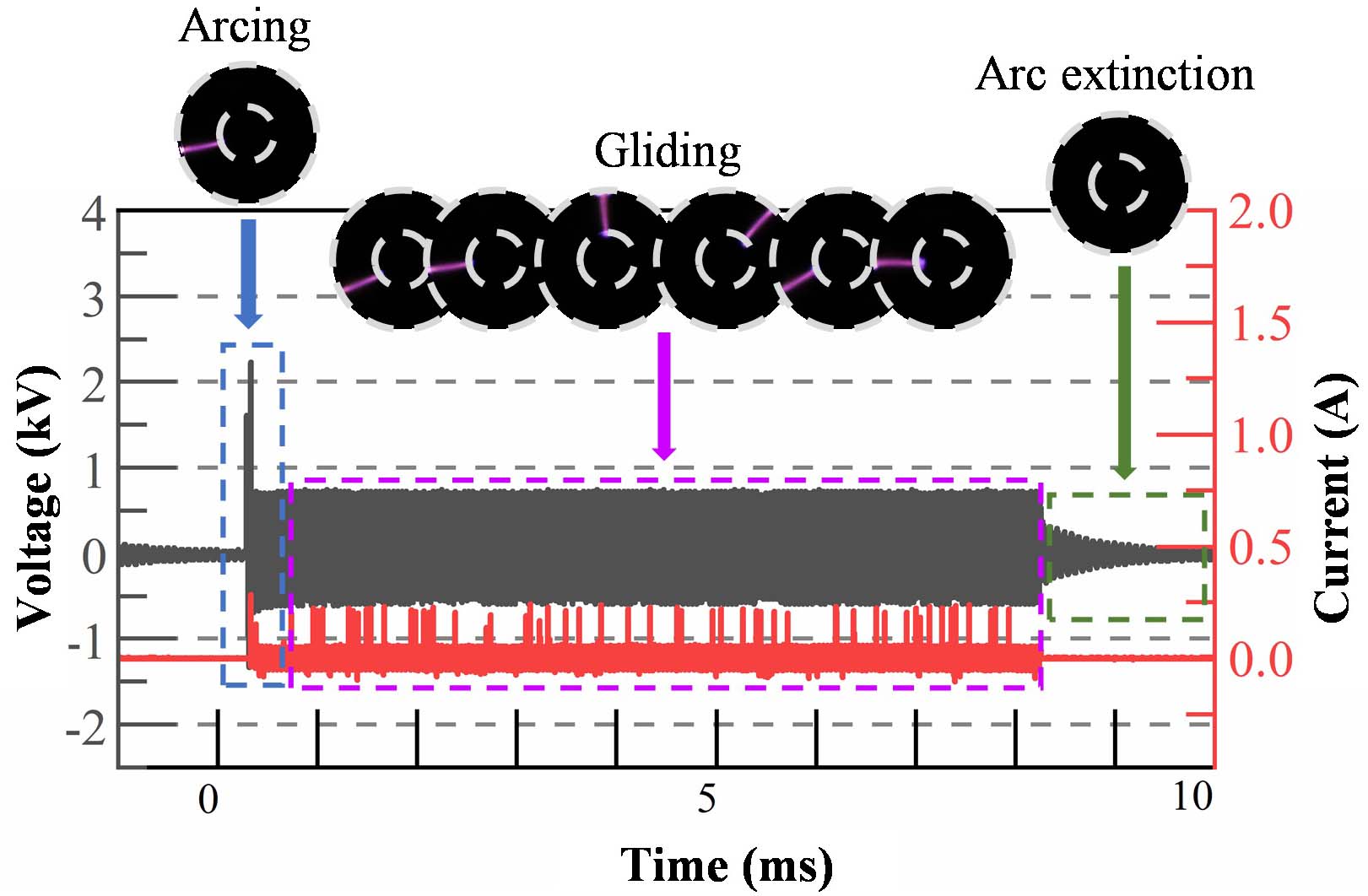
The MDRGA discharge device adopts a pulse-modulation power supply with a power frequency of 22.5 kHz and pulse-modulation frequency of 100 Hz. The peak-to-peak voltage of the power supply and the duty ratio of the pulse modulation are continuously adjustable. Images of the discharge process obtained using a high-speed camera are shown in the upper part of figure 2, with an exposure time of 0.25 ms.
The discharge image shows that the MDRGA discharge is a single arc rapidly gliding within the discharge gap, which is a dynamic arc discharge. The corresponding waveforms of the voltage and discharge current are shown in the lower part of figure 2. By comprehensively analyzing the arc image and waveforms of the voltage and discharge current, it can be seen that within a modulation period, the MDRGA discharge process can be divided into three stages: arcing, gliding, and arc extinction. When a high voltage is applied between the electrodes of the discharge device, the air in the discharge gap breaks down, forming an arc between the negative and positive electrodes. At this time, the corresponding current is higher, and the voltage decreases after the arc starts. Electrons and ions in the arc area move around the anode under the action of a magnetic field. In the original arc area, due to the removal of electrons and ions, there are no longer conditions for the continuous existence of the arc; therefore, the arc is extinguished. In the new area, due to the migration of electrons and ions, there is a favorable environment for discharge. When the voltage reaches the next peak, a new arc is formed. Therefore, the arc glides forward. Many researchers have also found in their own studies that the electrons and ions generated in the early stage of discharge contribute to the formation of arc in the later stage [19, 21, 25]. From the waveform of the current in figure 2, it can be observed that the amplitude of the subsequent discharge current is stable and decreasing. From a macroperspective, the arc glides steadily in the discharge space. After the excitation voltage ends, the arc ultimately extinguishes in the discharge space.
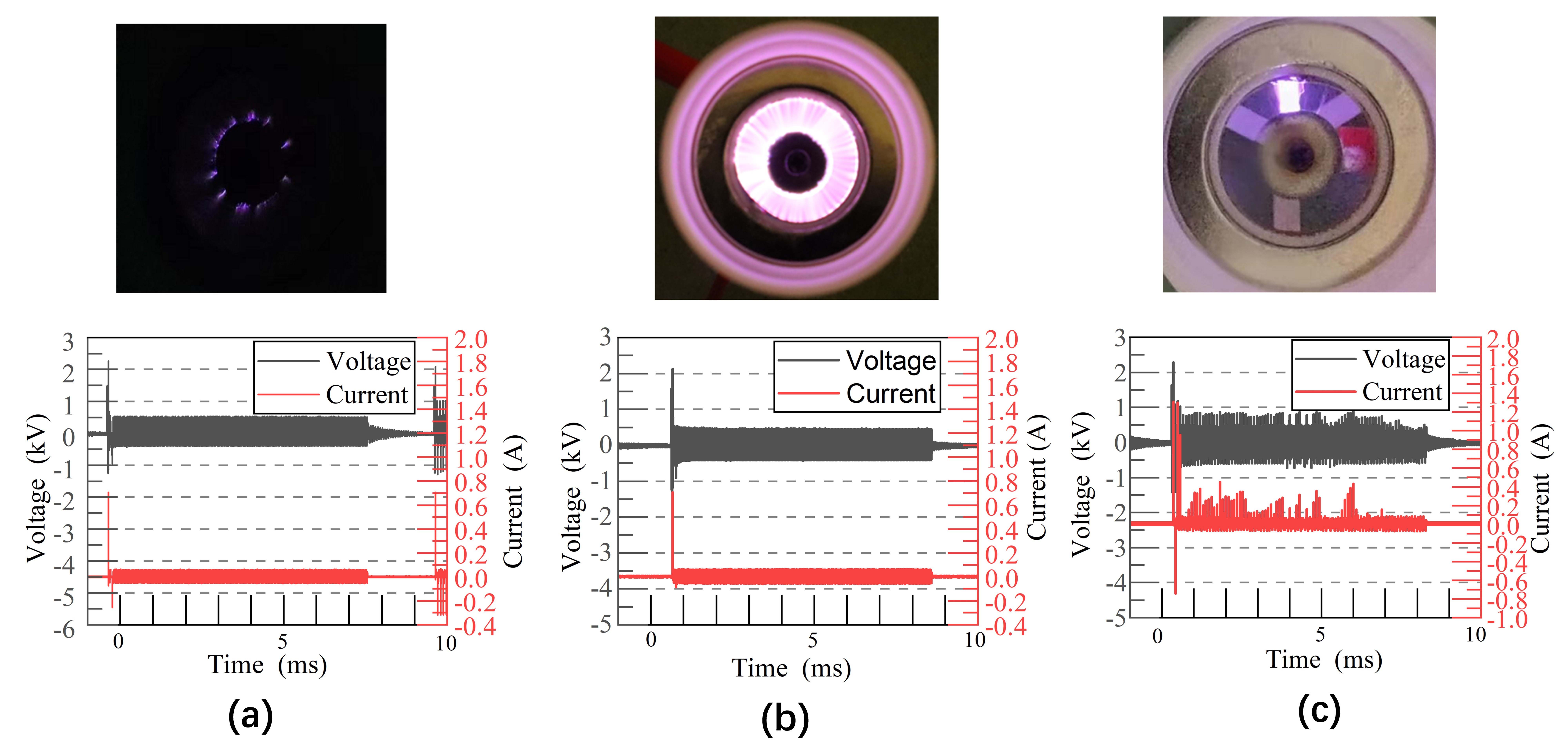
In the MDRGA discharge process, the power supply voltage has an important effect on the discharge process. The duty ratio is fixed at 80%, and the peak-to-peak voltage of the power supply is adjusted within the range of 6.0‒7.0 kV. It was found that both high and low voltages were not conducive to the formation of gliding arcs. Figure 3 shows the discharge images and corresponding waveforms of the voltage and discharge currents at different power supply voltages.
When the peak-to-peak voltage of the power supply is 6.0 kV, due to the low voltage, the air between the electrodes is not completely broken down, and there are only weak arc burrs at the edge of the tungsten sheet, similar to corona discharge. At this time, the discharge current is small, and this is called the ‘burr stage’. When the peak-to-peak voltage of the power supply is 6.5 kV, the air inside the discharge space is broken down to generate an arc, and the arc glides steadily inside the discharge space. The outermost aperture in the image is the reflection of the arc on the outer glass cover. The discharge performance is similar to that of glow discharge, where the discharge current is high and the current value is stable. This is called the ‘stable stage’. When the peak-to-peak voltage of the power supply is 7.0 kV, an arc is continuously generated in the discharge space, accompanied by a strong discharge sound, but the arc does not glide. The strong electric field is the main cause of air breakdown, and the residual electrons after the initial discharge are the secondary cause of arc formation. Therefore, the movement of electrons in the magnetic field cannot cause the arc to glide. At this time, the discharge current amplitude is high, and the current value fluctuates greatly. We call this the ‘strong breakdown stage’.
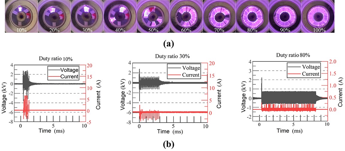
The power supply voltage was fixed at 6.7 kV, and the duty ratio was adjusted. It was found that the higher the duty ratio, the more conducive the formation of a gliding arc. Continuous images of the MDRGA discharge obtained through long exposure of the camera are shown in figure 4(a). When a high voltage of 6.7 kV was applied to both ends of the electrode, the air between the electrodes broke down and formed an arc. When the duty ratio is small, the duration of the high voltage is short and the number of electrons accumulated in the discharge space is relatively small, which has a small impact on gas breakdown and cannot form continuous discharge. Only discrete discharge is formed at certain points with a strong electric field, and it can be seen from the image that the arc does not glide. As the duty ratio increased, the duration of the high voltage increased, and the discharge time gradually increased. When the duty ratio exceeded 70%, the accumulation of electrons in the discharge channel significantly increased. These electrons reduce the energy required for gas breakdown, and discharge occurs in areas with a large number of electrons. As the electrons move laterally under the action of a magnetic field, a continuous discharge is formed in the discharge space, and it can be seen from the image that the arc glides steadily in the discharge space. By measuring the excitation voltage and current under different duty ratios, it was found that as the duty ratio increased, the discharge gradually stabilized and the amplitude of the discharge current gradually decreased. Figure 4(b) shows the waveforms of the discharge voltage and current at 10%, 30%, and 80% duty ratios. It can be observed from the figure that the amplitude of the discharge current is high for the first discharge of each modulation ratio. However, because of the presence of electrons left over from the previous discharge in air, electron avalanches in the gas are more likely to form, resulting in a significant decrease in current. From figure 4(b), it can be observed that the current at a 10% duty ratio is approximately 6 A, at 30% it is approximately 2.5 A, and at 80% it is only 0.3 A. It can be seen that as the duty ratio increases, the longer the discharge time per unit modulation period, the more residual electrons accumulate in the discharge space, the more stable the discharge, and the current gradually decreases and becomes smoother.
The simulation is mainly used to analyze the electromagnetic field of MDRGA, which can visually display the distribution of the magnetic field formed by the permanent magnet and analyze the influence of different power supply parameters on the electric field intensity. The physical field of MDRGA is composed of the electric field generated by the power supply and the magnetic field generated by the permanent magnet. Therefore, the electric and magnetic fields were selected as the physics interface in COMSOL Multiphysics. An AC/DC module was used in the simulation model.
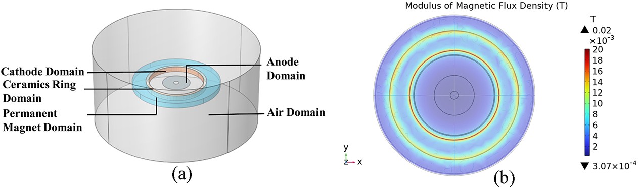
The three-dimensional model of MDRGA was established in the geometric window of COMSOL, and the model structure included multiple domains, such as the air, permanent magnet, ceramic ring, anode, and cathode domains. The model is illustrated in figure 5(a). The instantaneous voltage value V\mathit{\mathit{_{\mathrm{\mathit{t}}}}} is
| V\mathit{_{\mathrm{\mathit{t}}}}=V\mathrm{s}\mathrm{i}\mathrm{n}\left(2\text{π}ft+\theta\right), | (4) |
where V is the voltage amplitude, which is half of the peak-to-peak voltage; f is the AC frequency with a value of 22.5 kHz; t is time; and θ is the initial phase with a value of 0. The magnetic field intensity of the permanent magnet was 0.025 T, and the pulse-modulation period was 10 ms.
A stable and uniform magnetic field is the key factor for arc gliding. As shown in figure 5(b), the magnetic field exhibited a uniform distribution due to the presence of permanent magnets, and the maximum magnetic flux density was located at the edge of the magnet.
The distribution of the magnetic flux density in the MDRGA device along the radial direction is shown in figure 6(a), where h represents the distance from the surface of the magnet, i.e. the axial distance of the magnet. As shown in figure 6(a), in the discharge space from −10 to 10 mm along the x-axis, the magnetic flux densities at different heights were equal, which resulted in the particles in the arc being subjected to the same magnetic field force at different heights. As shown in figure 6(b), the direction of the magnetic induction line in the discharge space was vertically downward, which resulted in the radial direction of the magnetic field force. Particles of different heights were subjected to the same force, which ensured that the offset of the particles along the axis was the same, and the finer strip arc glided steadily along the radial direction, as shown in figure 2.
The electric field intensities under different voltages and duty ratios within a pulse-modulation period are shown in figure 7. We observed that as the peak-to-peak voltage increased, the electric field intensity uniformly increased. According to the Townsend discharge theory, the intensity of the electric field is the fundamental reason for the discharge. The stronger the electric field intensity, the easier it is to discharge. The experiments on the influence of voltage on discharge in figure 3 also show that a high voltage facilitates the generation of discharge. As the duty ratio increased, the duration of the voltage applied to the electrode increased, and the gliding time of the arc was also extended. From the experiments shown in figure 4, we found that the duty ratio affected the gliding time of the arc, but its correlation with the formation of the arc was weak.
In this study, we used a species of lactic acid bacteria, Lactobacillus fermentum, for sterilization experiments, which was provided by the Nano Microecology Laboratory of Guangdong the Greater Bay Area National Institute of Science and Technology Innovation Institute.
A flowchart of the sterilization experiment is shown in figure 8. First, the experimental liquid of fermented Lactobacillus was prepared and diluted with 0.9% NaCl normal saline, and the bacterial concentration was measured using a fluorescence spectrometer and adjusted to 1×10⁹ cfu mL–1. Five milliliters of bacterial solution was placed in a microbial aerosol generator. The microbial aerosol occurred in the front cavity of the plasma structure, and the reaction cavity was closed. A circulating fan with a diameter of 30 mm was placed in the front cavity of the discharge structure to drive the aerosol circulation flow inside the cavity. An exhaust fan was installed at the bottom of the sterilization unit. MRS solid agar medium was placed under the exhaust fan to collect the aerosol on the medium after sterilization, and the collection time was 2 min. After collection, the solid agar medium was covered with a sealing tape and then cultured in a 37 °C constant-temperature water bath incubator for 24 h. The colony growth state was then observed, and colony count was performed using an automatic colony counter.
The MDRGA discharging in the air produces ozone, which can effectively kill bacteria. The ozone tester was connected to the reaction cavity through a soft tube, and the concentrations of ozone under different duty ratios and voltages were measured after discharging for 5 s.
The power supply voltage was fixed at 6.7 kV, and the discharge time was fixed at 5 s. Figure 9(a) shows the ozone particle concentration under different pulse-modulation duty ratios. The results showed that the ozone concentration increased with an increase in duty ratio. The increase in duty ratio prolonged the discharge time, which can generate more ozone within one modulation period. The pulse-modulation duty ratio was fixed at 80%, and the discharge time was fixed at 5 s. Figure 9(b) shows the ozone particle concentration under different power supply voltages. The results showed that the ozone concentration generally increased with an increase in voltage but decreased at 6.7 kV.
In a plasma environment, the concentration of ozone is the result of the combined effects of the generation and decomposition processes. An increase in voltage promotes the ionization of oxygen atoms, which is beneficial for the generation of ozone. At the same time, an increase in voltage adds heat, which promotes the decomposition of ozone. The increase in voltage also promotes the formation of nitrogen oxides, which consume some oxygen atoms and ozone. Therefore, the ozone concentration will not continue to increase with the increase in voltage. Wei also found a similar phenomenon in the process of generating ozone through dielectric barrier discharge [26]. For MDRGA, the voltage also affects the gliding of the arc, which also affects the particle concentration. Therefore, the relationship between the ozone concentration and voltage is a complex nonlinear relationship.
Experiments were conducted on the sterilization effect of MDRGA using different parameters, such as sterilization time, power supply voltage, and pulse duty ratio. The power supply voltage was fixed at 6.7 kV, and the pulse-modulation duty ratio was fixed at 80%. The colony growth status and sterilization rate of the samples after different sterilization times are shown in figure 10. From the colony growth status in the culture medium, it can be observed that the aerosol samples without plasma treatment (0 s) had a larger number of colonies. After treatment with MDRGA discharge for 10‒30 s, the number of bacterial colonies significantly decreased. The average sterilization rate after 10 s was 86%. After 15 s of treatment, the sterilization rate increased significantly to 96% and continued to increase over time, but the growth rate gradually slowed down. After 25 s, the sterilization rate reached over 99%.
The power supply voltage was fixed at 6.7 kV, and the sterilization time was fixed at 20 s. The colony growth status and sterilization rate of the samples under different pulse-modulation duty ratios are shown in figure 11. From the colony growth status on the culture medium, it can be observed that the number of colonies significantly decreased with an increase in the pulse duty ratio, and the sterilization rate also showed an upward trend. From the variation curve of the sterilization rate, it can be observed that the sterilization rate increased significantly before 75%, and the rate of increase slowed down significantly after 75%. We can find similar trends in the experiments on the impact of duty ratio on discharge performance in section 3.1 and the simulation results regarding the impact of duty ratio on electric field intensity in section 3.2.
The pulse-modulation duty ratio was fixed at 80%, and the sterilization time was fixed at 20 s. The colony growth status and sterilization rate at different power supply voltages are shown in figure 12. The results revealed that the sterilization effect was the best when the voltage was 6.6 kV. Ultraviolet rays, strong electric fields, and various strongly active particles are the main factors in plasma sterilization [12‒14]. An increase in voltage enhances the electric field intensity, which is beneficial for sterilization. However, excessive voltage affects the gliding of the arc, thereby preventing the generation of charged particles, which is averse to sterilization. Therefore, the sterilization rate will not continue to increase with an increase in voltage, and an appropriate power supply voltage is an important condition for the efficient sterilization of MDRGA.
In this study, a novel MDRGA device was proposed for home air sterilization, which has the characteristics of a simple structure and stable performance. The influence of power supply parameters on discharge performance was studied through discharge experiments and simulation experiments, and the effects of power supply parameters on ozone concentration and sterilization effect were also analyzed. The experimental results showed that the MDRGA discharge process can be divided into three stages: arcing, gliding, and arc extinction. A high voltage is beneficial for arc formation; however, a continuously increasing voltage is not conducive to arc gliding. Therefore, a suitable voltage is the key factor for optimal sterilization effect; in this experiment, we chose 6.6 kV. An increase in the duty ratio is beneficial for the gliding of the arc, which also leads to an extension of the discharge duration and a high energy consumption.
The MDRGA has the advantages of a simple structure, stable discharge, and an effective sterilization effect, which is suitable for home air sterilization and has good application prospects. Plasma sterilization is a complex process, and in this study, we only examined the effects of voltage and duty ratios on its performance. In the future, it should be further studied from multiple aspects, such as device structure optimization, sterilization mechanism, and other parameters. This will advance the progress in plasma sterilization.
This study was supported by National Natural Science Foundation of China (Nos. 52077129 and 52277150) and the Natural Science Foundation of Shandong Province (No. ZR2022ME037).
| [1] |
Pan J et al 2022 J. Phys. D: Appl. Phys. 55 035202 doi: 10.1088/1361-6463/ac2ad8
|
| [2] |
Yin B, Zhu Y F and Wu Y 2023 High Volt. 8 1168 doi: 10.1049/hve2.12348
|
| [3] |
Li J Y et al 2022 Curr. Appl. Phys. 34 41 doi: 10.1016/j.cap.2021.11.004
|
| [4] |
Wang L P et al 2023 Phys. Scr. 98 045605 doi: 10.1088/1402-4896/acbe75
|
| [5] |
Gao Y T et al 2023 J. Phys. D: Appl. Phys. 56 495203 doi: 10.1088/1361-6463/acf325
|
| [6] |
Wang X L et al 2023 High Volt. 8 841 doi: 10.1049/hve2.12351
|
| [7] |
Shen J F et al 2022 Proc. CSEE 42 8781 (in Chinese) doi: 10.13334/j.0258-8013.pcsee.212248
|
| [8] |
Zhang S et al 2022 High Volt. 7 718 doi: 10.1049/hve2.12201
|
| [9] |
Bai C J et al 2022 High Volt. Eng. 48 1142 (in Chinese) doi: 10.13336/j.1003-6520.hve.20210250
|
| [10] |
Kuang Y et al 2023 Trans. China Electrotech. Soc. 38 3960 (in Chinese) doi: 10.19595/j.cnki.1000-6753.tces.221939
|
| [11] |
Pan J et al 2023 Energy Convers. Manage. 277 116620 doi: 10.1016/j.enconman.2022.116620
|
| [12] |
Xiong Z L, Lu X P and Xao Y G 2011 Sci. Sin. Technol. 41 1279 (in Chinese) doi: 10.1360/092011-717
|
| [13] |
Chen X Y et al 2022 Plasma Sci. Technol. 24 124015 doi: 10.1088/2058-6272/aca06e
|
| [14] |
Zhu B et al 2023 Plasma Sci. Technol. 25 015505 doi: 10.1088/2058-6272/ac7db9
|
| [15] |
Wu Q et al 2021 High Volt. Eng. 47 826 (in Chinese) doi: 10.13336/j.1003-6520.hve.20201182
|
| [16] |
Zhao H et al 2023 High Volt. Eng. 49 5270 (in Chinese) doi: 10.13336/j.1003-6520.hve.20221668
|
| [17] |
Li H et al 2022 Plasma Sci. Technol. 24 045501 doi: 10.1088/2058-6272/ac550d
|
| [18] |
Mackinder M A et al 2020 Clin. Plasma Med. 17‒18 100092
|
| [19] |
Zhang L et al 2022 Acta Phys. Sin. 71 075204 (in Chinese) doi: 10.7498/aps.71.20211232
|
| [20] |
Chen J et al 2022 High Volt. Eng. 48 3794 (in Chinese) doi: 10.13336/j.1003-6520.hve.20211602
|
| [21] |
Lei J P et al 2020 Acta Phys. Sin. 69 195203 (in Chinese) doi: 10.7498/aps.69.20200672
|
| [22] |
Ding L et al 2021 Proc. CSEE 41 2939 (in Chinese) doi: 10.13334/j.0258-8013.pcsee.202263
|
| [23] |
Wang C et al 2019 Plasma Chem. Plasma Process. 39 259 doi: 10.1007/s11090-018-9937-8
|
| [24] |
Zhang Y Q et al 2013 J. Zhejiang Univ. (Eng. Sci.) 47 687 (in Chinese) doi: 10.3785/j.issn.1008-973X.2013.04.019
|
| [25] |
Liu J B 2021 Study on discharge mode and CO2 reduction reaction with H2 in magnetically driven gliding arc plasma PhD Thesis Dalian University of Technology, Dalian, China (in Chinese)
|
| [26] |
Wei L S 2008 Theoretical and experimental research on ozone generation by gas discharge plasma PhD Thesis Zhejiang University, Hangzhou, China (in Chinese)
|
Supported by: Beijing Renhe Information Technology Co., Ltd. 
 DownLoad: