Figure
1.
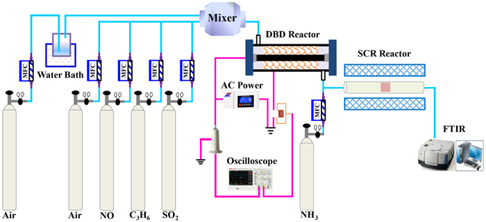
Schematic diagram of NH3-SCR assisted by NTP.
| Citation: |
Tao ZHU, Xing ZHANG, Zhenguo LI, Xiaoning REN, Baodong WANG, Xuyang CHONG, Hongli MA. Selective catalytic reduction of NOx with NH3 assisted by non-thermal plasma over CeMnZrOx@TiO2 core–shell catalyst[J]. Plasma Science and Technology, 2022, 24(5): 054006. DOI: 10.1088/2058-6272/ac3108

|
The presented work reports the selective catalytic reduction (SCR) of NOx assisted by dielectric barrier discharge plasma via simulating marine diesel engine exhaust, and the experimental results demonstrate that the low-temperature activity of NH3-SCR assisted by non-thermal plasma is enhanced significantly, particularly in the presence of a C3H6 additive. Simultaneously, CeMnZrOx@TiO2 exhibits strong tolerance to SO2 poisoning and superior catalytic stability. It is worthwhile to explore a new approach to remove NOx from marine diesel engine exhaust, which is of vital significance for both academic research and practical applications.
With the rapid development of the transportation industry, the emission of high-power marine diesel engine exhaust has aroused widespread concern from all over the world. The marine diesel engine mainly uses heavy fuel oil with high sulfur as fuel, and its major pollutants are NOx and SO2, which not only destroy the ecological environment but also pose great threats to human beings. The selective catalytic reduction of NOx with ammonia (NH3-SCR) is the most effective technology to remove NOx from marine diesel engine exhaust, and has been successfully applied in the field of mobile source exhaust for several years [1–4]. V2O5–WO3/TiO2 has been commercially used in the exhaust treatment of marine diesel engines, but several issues have severely impeded its further application. The main obstacles of V-based catalysts are the narrow operating temperature window, high SO2 oxidation activity and biological toxicity of V species. In addition, the exhaust temperature of a marine diesel engine is usually between 150 ℃ and 200 ℃ [5, 6]. Previous studies have reported that Ce- and Mn-based SCR catalysts boast remarkable low-temperature activity on account of their superior performance in the store–release of O and excellent redox ability. However, they are easily deactivated in the presence of SO2 because (NH4)2SO4, NH4HSO4 and metal sulfates can block and destroy the active sites [7, 8]. In these circumstances, constructing an SCR catalyst with core–shell structure could improve the SO2 tolerance effectively [9–11]. Gan et al synthesized a MnOx@CeO2 core–shell catalyst using the chemical deposition method, and it exhibited excellent low-temperature activity and strong SO2 tolerance. Further research showed that the high activity could be attributed to the rich Mn4+/Ce3+ species and highly crystalline α-MnO2, while the strong tolerance to SO2 was ascribed to the CeO2 shell that protected the active α-MnOx species from been poisoned [12].
Non-thermal plasma (NTP) has been confirmed to be a prospective technology for the removal of NOx, which offers an unconventional way to initiate chemical reactions in gases and liquids but suffers from low selectivity when it is used alone [13, 14]. Currently, plasma catalysis has been a hot topic of research on account of its potential for applications in a wide range of chemical reaction, environmental protection and energy-related processes. Moreover, the coupling of plasma and catalysis can steer the reactions in the desired direction, thus providing improved selectivity and reducing unwanted by-products. Overall, plasma catalysis can improve energy efficiency and product selectivity, and sometimes it shows a synergistic effect, which promotes low-temperature activity while providing a high NOx conversion in a wide operating window [15–18]. During the removal of NOx, NTP generates plenty of reactive O species (ROS), such as ·O and ·OH, and NO can be oxidized to NO2 by ROS. A fast SCR reaction (equation (2)) occurs when the amounts of NO and NO2 are equimolar in an NTP system, and its reaction efficiency is faster than that of the standard SCR reaction (equation (1)) [19, 20].
| 4NO+4NH3+O2→4N2+6H2O | (1) |
| 2NO+2NO2+4NH3→4N2+6H2O | (2) |
There are two combinations of NTP and NH3-SCR: in-plasma catalysis (IPC) and post-plasma catalysis (PPC). IPC is usually called a single-stage plasma-catalytic system, in which the SCR catalyst is placed in the discharge zone, and its advantage is that active species can react on the SCR catalyst surface. In contrast, PPC is called a two-stage configuration, which involves placing the SCR catalyst downstream from the NTP. The oxidation of NO to NO2 in NTP increases SCR catalytic performance in the two-stage configuration because the NO2 removal is better than NO removal near the SCR catalyst [21–24]. This work reports the deNOx performance and catalytic stability of an NTP-SCR system to reveal the effect of influencing parameters on NOx conversion via placing a CeMnZrOx@TiO2 core–shell catalyst downstream from NTP. It is of great significance to investigate the NOx conversion of NH3-SCR assisted by NTP, which can provide technical guidance and theoretical support to remove NOx from marine diesel engine exhaust.
There are two steps in the preparation of the CeMnZrOx@TiO2 catalyst. Firstly, for the CeMnZrOx core a sol–gel method was adopted. The molar component loading of Ce: Mn: Zr was 7:2:1, and the corresponding Ce(NO3)2, Mn(NO3)2 and Zr(NO3)2 were dissolved in the deionized water. In addition, the C6H8O7 was added at a 1:1 ratio, and the mixture was peptized by stirring for 6 h at room temperature to form a highly dispersed CeMnZrOx sol. After that, it was dried into gel at 100 ℃ for 12 h, followed by calcination in the muffle furnace at 500 ℃ for 4 h to obtain a CeMnZrOx catalyst. Secondly, 300 mg CeMnZrOx catalyst was dispersed in 400 ml ethanol. Subsequently, 36 ml tetrabutyl titanate and 3 ml hydrous ammonia were added separately and stirred continuously for 4 h at 60 ℃. The sample was obtained by centrifugation, washed with ethanol and dried at 100 ℃ for 12 h, followed by calcination 500 ℃ for 4 h. Finally, all samples were pressed, crushed and sieved to 40–60 meshes for catalytic evaluation of NH3-SCR assisted by NTP.
The morphology analysis of the SCR catalysts was characterized by scanning electron microscopy (SEM, JEOL, Japan). The specific surface area of the SCR catalysts was determined by the Brunauer–Emmett–Teller (BET) method, and the pore volume and average pore diameter of the SCR catalysts were obtained from the desorption curve using the Barrett–Joyner–Halenda (BJH) method. Prior to the measurements, all samples were outgassed for 12 h at 200 ℃ in a vacuum. X-ray diffraction (XRD) measurements were carried out on an XRD–7000 S (Shimadzu Corporation, Japan), which was operated at 40 kV and 40 mA using Cu Kα radiation. The scanning angle (2θ) scans ranged from 10° to 80° with a step of 0.02°, and the scanning speed was 5° min–1. H temperature-programmed reduction (H2-TPR) measurements of the SCR catalysts were performed using a Micromeritics AutoChem Ⅱ 2920 chemisorption analyzer with a thermal conductivity detector (TCD). A 100 mg quantity of the catalyst was preprocessed at 200 ℃ for 1 h under Ar atmosphere and then cooled to room temperature. After that, the temperature was raised to 800 ℃ at 10 ℃ min-1 with a flow of H2 (10%)/Ar (50 ml min-1). Temperature-programmed desorption by ammonia (NH3-TPD) experiments were carried out on the Micromeritics AutoChem Ⅱ 2920. 100 mg catalyst was pretreated at 500 ℃ for 1 h in N2 (50 ml min-1) and cooled down to 120 ℃, then 10% NH3/N2 (50 ml min-1) was passed through the catalyst bed for 1 h to obtain saturation. After purging with N2 for 1 h, the temperature was increased to 800 ℃ at a rate of 10 ℃ min-1.
The schematic diagram of NH3-SCR assisted by NTP is shown in figure 1. The reaction gas mixture simulated the marine diesel engine exhaust, which consisted of 500 ppm NO, 500 ppm NH3, 0–300 ppm C3H6 (when used), 100 ppm SO2 (when used), and air as the balance gas. The total flow rate of feed gas was kept constant at 500 ml min-1, corresponding to a gas hourly space velocity (GHSV) of 30 000 h-1. The concentration of NOx (NOx =NO+NO2), N2O and NH3 in the inlet and outlet gas was analyzed by a Fourier-transform infrared spectrometer (FT-IR, Shimadzu IRTracer–100). The NTP adopted DBD plasma reactor was powered by an alternating current (AC), and the output waveform was observed on an UNI–T UPO3254CS oscilloscope. A 1.0 ml quantity of SCR catalyst was employed, which was placed downstream from the NTP, and the reaction temperature was maintained at 150 ℃ in order to simulate the actual condition of marine diesel engine exhaust. The mathematical expressions for NOx conversion and N2 selectivity are as follows:
| NOxconversion(%)=NOx,in-NOx,outNOx,in×100% | (3) |
| N2selectivity(%)=1-2N2OoutNOx,in-NOx,out+NH3,in-NH3,out×100% | (4) |
where
The catalytic evaluations of the CeMnZrOx@TiO2 and CeMnZrOx catalysts were tested three times, and if the experimental data fluctuated by more than 10%, it was discarded. Otherwise, it was averaged. The error bar was used as an index to evaluate the difference between the average and the measurement.
| Na=N1+N2+N33 | (5) |
| Errorbar=∑3i=1|Ni-Na|3 | (6) |
where
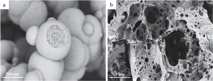
Figure 2 displays the SEM images of the CeMnZrOx@TiO2 and CeMnZrOx catalysts. As depicted in figure 2(a), the CeMnZrOx@TiO2 core–shell structure catalyst presents a spherical particle and relatively smooth surface, and the outer surface is coated by a TiO2 shell. By contrast, the CeMnZrOx catalyst possesses a loose structure and rich porosity, which is beneficial for the high dispersion of metal oxides on the CeMnZrOx surface [25]. The BET surface area, pore volume and average pore diameter results of the SCR catalysts are summarized in table 1. Visibly, the BET surface area of the CeMnZrOx@TiO2 catalyst is higher than that of CeMnZrOx, and the pore volume and average pore diameter of CeMnZrOx@TiO2 are about 0.124 cm3 g-1 and 1.98 nm, respectively.
| SCR catalysts | BET surface area (m2 g-1) | Pore volume (cm3 g-1) | Average pore diameter (nm) |
| CeMnZrOx@TiO2 | 87±0.76 | 0.124±0.01 | 1.98±0.02 |
| CeMnZrOx | 82±0.83 | 0.139±0.02 | 2.16±0.01 |
 DownLoad:
CSV
DownLoad:
CSV
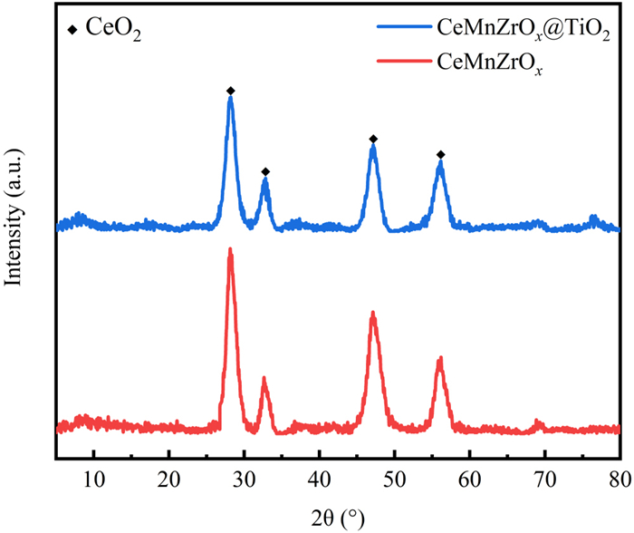
The XRD patterns of the CeMnZrOx@TiO2 and CeMnZrOx catalysts are presented in figure 3. As illustrated in figure 3, the CeMnZrOx@TiO2 catalyst only exhibits CeO2 crystalline phase, and the signals of MnOx, ZrO2 and anatase TiO2 phases are not observed over CeMnZrOx@TiO2, which means that the MnOx, ZrO2 and TiO2 species are homogeneously dispersed on the surface of CeMnZrOx@TiO2 as amorphous oxides or aggregated in minicrystals that are too small to be detected by XRD. Moreover, it is worth mentioning that the intensity of the diffraction peak attributed to CeO2 crystalline phase over CeMnZrOx@TiO2 is reduced markedly compared to CeMnZrOx, which may be attributed to the coating of the TiO2 shell.
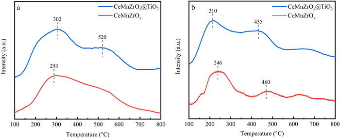
Figure 4(a) illustrates the NH3-TPD curves of the CeMnZrOx@TiO2 and CeMnZrOx catalysts in the temperature range of 100 ℃–800 ℃. As plotted in figure 4(a), it is obvious that the CeMnZrOx@TiO2 catalyst demonstrates two NH3 desorption peaks at 302 ℃ and 520 ℃, respectively. In addition, the NH3 desorption signal of CeMnZrOx catalyst occurs at 293 ℃, which exhibits a board peak ranging from 100 ℃ to 800 ℃. The H2-TPR profiles of CeMnZrOx@TiO2 and CeMnZrOx catalysts are presented in figure 4(b), and it can be seen that there are two reduction peaks at 210 ℃ and 435 ℃, respectively, which can be attributed to the reduction of CeO2 and MnOx. Furthermore, it can be observed that the reduction peak of the CeMnZrOx@TiO2 catalyst moves toward lower temperature, and the peak area of the CeMnZrOx@TiO2 catalyst is larger than that of CeMnZrOx as elucidated in table 2, which indicates that there are more reductive sites in the surface of CeMnZrOx@TiO2.
| Samples | NH3 consumptiona (μmol g-1) | H2 consumptionb (μmol g-1) |
| CeMnZrOx@TiO2 | 95.4 | 1349 |
| CeMnZrOx | 73.6 | 1085 |
| NH3 consumption derived from NH3-TPD data. H2 consumption calculated from H2-TPR data. | ||
DownLoad:
CSV
The discharge power of the DBD reactor was determined by checking the charge–voltage (Q–U) Lissajous, and the specific energy input of the NTP system was calculated in the following equations (7) and (8).
| P=1T∫T0u(t)i(t)dt=CmT∫T0duc(t)dtdt=fCm·A | (7) |
| SEI=60PQ | (8) |
P represents the discharge power (W). T is the period of the discharge cycle (s). u(t) is the high voltage applied between electrodes (kV). i(t) is the current change with time (A). f is the discharge frequency of the AC power signal (Hz). uc(t) is the voltage at both ends of Cm (kV). Cm is the measuring capacitance, which is equal to 0.36 μF. A is the area of Q–U Lissajous graphics. SEI represents the specific energy input of the reaction system (J l-1). Q signifies the total gas flow rate (l min-1).
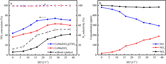
The effect of SEI on NOx conversion and N2 selectivity in the NTP-SCR system is shown in figure 5(a). Obviously, the NOx conversion is very low if using NTP alone because NO is mostly converted into NO2 in the NTP gas-phase reaction, and NO2 does not react with NH3 adequately to generate N2 and H2O without an SCR catalyst. The conclusion of NO being oxidized to NO2 can be drawn from figure 5(b). In addition, the N2 selectivity is also poor due to the reactions of (9) and (10). Furthermore, it can be seen that the NOx conversions of CeMnZrOx@TiO2 and CeMnZrOx are just 43.9% and 36.2% without NTP, respectively. In sharp contrast to this result, the NOx conversion improves gradually with the increase of SEI when NTP is operated, and the NOx conversion of CeMnZrOx@TiO2 reaches the maximum value of 73.96% at an SEI of 28 J l-1. However, the NOx conversion increases slowly when the SEI exceeds 28 J l-1, which might be ascribed to the enhanced reverse reaction (equation (24)) due to the presence of a higher concentration of atomic O species.
In the NTP-SCR system, NO can be oxidized by atomic O species generated by the NTP gas-phase reaction, which is beneficial to the SCR reaction to a certain degree. Zhao et al revealed that the rate constant of O2 dissociation by electron collision reactions was almost two orders of magnitude higher than that of N2 dissociation, and the concentration of atomic O species increases with increasing SEI. In this case, the rate constants of NOx conversion decreased with increasing atomic O species concentration because the atomic O species were electronegative and thus reduced electron concentration [26]. The above experimental phenomenon is consistent with the research of Jiang et al [27], who also found that the heat effect caused by NTP had a negligible impact on enhanced NOx conversion, while the intermediates generated in the NTP system might significantly contribute to the improved SCR catalytic performance of NOx on the catalyst surface in the NH3-SCR process. Moreover, the N2 selectivity is maintained at 100%, which is almost independent of SEI. The by-products of N2O and N2O5 are not detected in the outlet gas, which indicates that the NH3-SCR assisted by NTP does not cause secondary pollution. The following chemical reactions occur in the NTP-SCR system according to the relevant reports [28–30].
| 4NH3+4NO→4N2O+6H2O | (9) |
| 2NH3+2O2→N2O+3H2O | (10) |
| 4NH3+3O2→2N2+6H2O | (11) |
| 4NH3+5O2→4N2+6H2O | (12) |
| 8NH3+6NO2→7N2+12H2O | (13) |
| 2NH3+2NO2→N2+NH4NO3+H2O | (14) |
| O2+e→O2*+e | (15) |
| O2*→O+O | (16) |
| O2+O→O3 | (17) |
| N2+e→N2*+e | (18) |
| N2*→N+N | (19) |
| NO+O→NO2 | (20) |
| NO+N→N2+O | (21) |
| NO2+N→N2O+O | (22) |
| N2O+O→N2+O2 | (23) |
| NO2+O→NO+O2 | (24) |
| NO+O3→NO2+O2 | (25) |
| N2O+O3→2NO+O2 | (26) |
| NO2+O3→NO3+O2 | (27) |
| NO3→NO+O2 | (28) |
| NO+NO3→2NO2 | (29) |
| NO2+NO3→N2O5 | (30) |
where
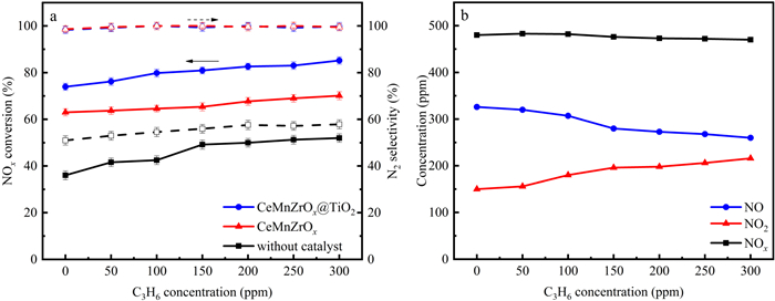
Previous studies have demonstrated that hydrocarbons can be attributed an important role in the removal of NOx using NTP technology, and the reaction paths for NOx removal can change significantly from those without hydrocarbon additives. C3H6 is a representative hydrocarbon on account of its superior efficiency of NO oxidation, which can significantly enhance NO to NO2 conversion performance as an essential step for the subsequent NH3-SCR reaction paralleled with economy in the input energy cost. Therefore, the effect of C3H6 on NOx conversion over CeMnZrOx@TiO2 and CeMnZrOx catalysts was investigated at 28 J l-1, and figure 6 indicates the detailed results. Clearly, it can be seen that the NOx conversion improves greatly when introducing the C3H6 additive to the NTP-SCR system due to the reactions between the hydrocarbons and NOx. Meanwhile, the concentration of NO2 increases significantly in the NTP gas-phase reaction as depicted in figure 3, which is beneficial for the fast SCR reaction in the subsequent device. The experimental result is similar to the research of Jiang et al [27], who reported that the NOx conversion improved gradually with increasing C3H6 concentration, and that the addition of C3H6 not only promoted the conversion of NO into NO2 in the NTP system but also enhanced the catalytic reduction of NOx on the catalyst surface. Further research found that the oxidation of C3H6 with O atoms could generate oxygenates in first-stage plasma, and there might be two effects that could result in the enhanced reduction of NOx. On one hand, the O atoms might be consumed by C3H6, which limits the reverse reaction equation (24). On the other hand, NO might react with oxygenates to produce N2, as shown in equation (38). Guan et al also found that the NOx removal efficiency was improved significantly at lower temperatures in the NH3-SCR system because C3H6 could be decomposed into useful intermediates such as methyl, methoxy radicals, and partial oxidation products of C3H6 conversion, including peroxyl radicals and hydro-peroxy radicals [31]. In the presence of C3H6, specific pathways between NO and hydrocarbons could occur in the NTP-SCR system, such as the following chemical reactions [32–34]:
| C3H6+O→C2H5+HCO | (31) |
| C3H6+O→C2H2+CH3O+H | (32) |
| C3H6+O→CH2+CH3+HCO | (33) |
| HCO+O2→HO2+CO | (34) |
| C2H5+O2→C2H5O2 | (35) |
| CH3+O2→CH3O2 | (36) |
| CH3O+O2→CH2O+HO2 | (37) |
| NO+HO2→NO2+OH | (38) |
| NO+C2H5O2→NO2+CH3CH2O | (39) |
| NO+CH3O2→NO2+CH3O | (40) |
| C3H6+OH→C3H6OH | (41) |
| C3H6OH+O2→C3H6OHOO | (42) |
| C3H6OHOO+NO→C3H6OHO+NO2 | (43) |
| (8x+2y-4z)NO+4CxHyOz→(4x+y-2z)N2+4xCO2+2yH2O | (44) |
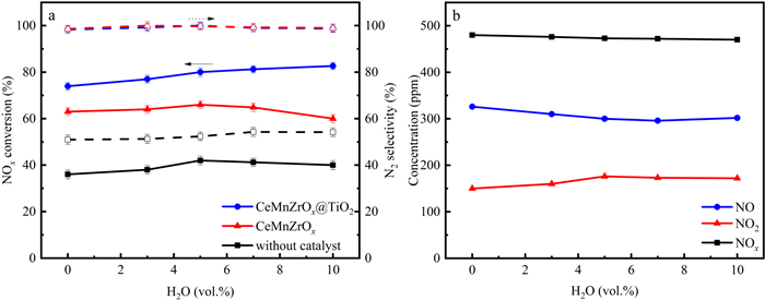
It is noted that in practical applications, H2O is an inevitable combustion product in marine diesel engine exhaust and could generate a variety of strong oxidizing free radicals though NTP gas-phase reaction, which usually contributes to the oxidative removal of NOx [35]. Numerous investigations have indicated that the conversion of NO to NO2 is an important intermediate step in the reduction of NOx to N2, and the most efficient approach to achieve it is using NTP combined with an SCR catalyst. First of all, NO is oxidized to NO2 in the presence of HC and H2O using NTP technology. Then, the catalyst reduces NO2 to N2 by selective reduction using NH3 as a reductant. However, the adsorbed H2O molecules can consume high-energy electrons due to their electronegativity, and the specific energy input of the NTP system declines significantly when the H2O content exceeds the limit [36–38]. Beyond that, H2O can also poison and deactivate the catalyst by inhibition of the active sites. In light of the characteristics of marine diesel engine exhaust, the effect of H2O on NOx conversion at a specific energy input of 28 J l-1 was investigated under different H2O contents of 0, 3 vol.%, 5 vol.%, 7 vol.% and 10 vol.%. As can be seen from figure 7, the NOx conversion over CeMnZrOx@TiO2 increases slightly from nearly 73.96% to about 82.67% when H2O is added to the NTP-SCR system. However, the NOx conversion over CeMnZrOx increases first and then decreases when the H2O concentration ranges from 0 to 10 vol.%. That is because H2O can inhibit the removal of NOx due to the competitive adsorption of NO, NH3 and H2O on the active sites, and it gives the conclusion that the TiO2 shell of CeMnZrOx@TiO2 can prevent the adsorption of H2O. Similarly, the concentration of NO2 increases slightly when adding an appropriate amount of H2O to the NTP-SCR system. Jiang et al reported that another reaction pathway for NOx removal exists on the SCR catalyst surface in the presence of H2O [27]. The related chemical reactions are involved when there is H2O in the NTP system according to the relevant reports, which are as follows [39–42]:
| H2O+e→OH+H+e | (45) |
| H2O+e→H+H+O+e | (46) |
| H2O+O→OH+OH | (47) |
| H+O2→HO2 | (48) |
| OH+OH→H2O2 | (49) |
| NO+OH→HNO2 | (50) |
| NO2+H2O→HNO3 | (51) |
| NO+H2O→NO2+OH | (52) |
| NO+HO2→NO2+OH | (53) |
| H2O2+OH→HO2+H2O | (54) |
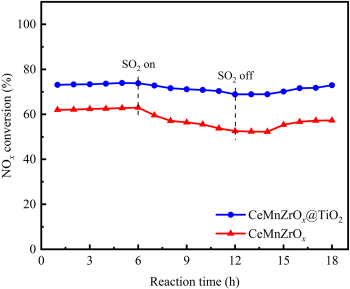
It is generally acknowledged that SO2 easily forms unstable sulfite ions and further reacts with adsorbed O to generate metal sulfates, which seriously inhibit the catalytic activity of the SCR catalyst and eventually lead to SCR catalyst deactivation [43–46]. The SO2 tolerance of the CeMnZrOx@TiO2 and CeMnZrOx catalysts at a specific energy input of 28 J l-1 was explored in the presence of 100 ppm SO2, and the detailed results are presented in figure 8. As depicted in figure 8, the catalytic activity of CeMnZrOx@TiO2 decreased slightly after introducing the SO2, and then remained almost constant. After that, the NOx conversion recovered to the original level and remained stable for 6 h when the SO2 was removed, which demonstrated that the addition of SO2 had little effect on the SCR activity of CeMnZrOx@TiO2. By contrast, the NOx conversion of CeMnZrOx was severely suppressed when SO2 was added to the NTP-SCR system, and the NOx conversion of that was restored to a certain extent but was lower than the initial value when the SO2 was cut off. Combined with the above observations, the CeMnZrOx@TiO2 core–shell catalyst possesses a stronger tolerance to SO2 than CeMnZrOx, and it can be deduced that the formation of (NH4)2SO4, NH4HSO4 and metal sulfates may be restrained due to the presence of the TiO2 shell, which can react with SO2 and serve as a protective layer.
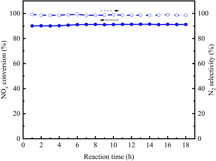
The long-time stability is of vital importance for the SCR catalyst in the NTP-SCR system and can provide a valuable reference for practical applications. The catalytic stability of CeMnZrOx@TiO2 at a GHSV of 20 000 h-1 was evaluated in this section. The stability test was carried out at an specific energy input of 28 J l-1, and the tested concentrations of NO, NH3, C3H6 and SO2 were 500 ppm, 500 ppm, 300 ppm and 100 ppm, respectively. The H2O concentration was kept at 10%, and the experimental result is depicted in figure 9. As can be seen from figure 9, the running time of the whole progress was 18 h without interruption, and the result of this continuous test illustrated that the activity of CeMnZrOx@TiO2 depressed little within 18 h of reaction. Remarkably, the NOx conversion was maintained at 91.25% during the test period, which indicates that the CeMnZrOx@TiO2 catalyst exhibits superior catalytic stability over the entire range of the time frame investigated. The good stability of the CeMnZrOx@TiO2 catalyst in the NTP-SCR system provides the possibility for practical elimination of NOx from marine diesel engine exhaust.
This work has verified that the catalytic performance of NH3-SCR assisted by NTP for NOx removal is an effective approach, and the NOx conversion of CeMnZrOx@TiO2 is enhanced significantly when assisted by NTP compared to the catalytic activity of NH3-SCR without NTP, even in the presence of C3H6 and H2O. The CeMnZrOx@TiO2 core–shell structure catalyst possesses excellent low-temperature activity and superior catalytic stability in the NTP-SCR system, and it exhibits strong tolerance to SO2 poisoning because the TiO2 shell prevents the generation of (NH4)2SO4, NH4HSO4 and metal sulfates from blocking the active sites. It is expected that this work can provide a new strategy for the removal of NOx from marine diesel engine exhaust and it has huge potential for industrial applications in the future.
This workwas supported by National Key Research and Development Project of China (No. 2019YFC1805503), National Engineering Laboratory for Mobile Source Emission Control Technology (No. NELMS2019A13), the Open Project Program of the State Key Laboratory of Petroleum Pollution Control (No. PPC2019013), and Major Science and Technology Projects of Shanxi Province (No. 20181102017).
| [1] |
Verschaeren R and Verhelst S 2018 Energy 147 681 doi: 10.1016/j.energy.2018.01.081
|
| [2] |
Ovaska T et al 2019 Appl. Therm. Eng. 150 1168 doi: 10.1016/j.applthermaleng.2019.01.090
|
| [3] |
Xi H Y et al 2020 J. Hazard. Mater. 399 123069 doi: 10.1016/j.jhazmat.2020.123069
|
| [4] |
Deng J J et al 2021 Sci. Total. Environ. 766 144319 doi: 10.1016/j.scitotenv.2020.144319
|
| [5] |
Li Y L et al 2020 Appl. Catal. B: Environ. 268 118455 doi: 10.1016/j.apcatb.2019.118455
|
| [6] |
Liang Q M, Li J and Yue T 2021 Environ. Sci. Technol. 21 101209 doi: 10.1016/j.eti.2020.101209
|
| [7] |
Zhu T et al 2020 Catalysts 10 135 doi: 10.3390/catal10010135
|
| [8] |
Han L P et al 2019 Chem. Rev. 119 10916 doi: 10.1021/acs.chemrev.9b00202
|
| [9] |
Huang B J et al 2017 J. Environ. Sci. 55 129 doi: 10.1016/j.jes.2016.05.038
|
| [10] |
Chen L et al 2019 Chem. Eng. J. 369 957 doi: 10.1016/j.cej.2019.03.055
|
| [11] |
Han L P et al 2019 Environ. Sci. Technol. 53 6462 doi: 10.1021/acs.est.9b00435
|
| [12] |
Gan L N et al 2020 Chem. Eng. J. 391 123473 doi: 10.1016/j.cej.2019.123473
|
| [13] |
Gholami R et al 2018 Philos. T. R. Soc. A 376 20170054 doi: 10.1098/rsta.2017.0054
|
| [14] |
Peters F et al 2016 Plasma Sci. Technol. 18 406 doi: 10.1088/1009-0630/18/4/13
|
| [15] |
Zhu T et al 2020 Plasma Sci. Technol. 22 034011 doi: 10.1088/2058-6272/ab618b
|
| [16] |
Talebizadeh P et al 2014 Renew. Sust. Energ. Rev. 40 886 doi: 10.1016/j.rser.2014.07.194
|
| [17] |
Pan H and Qiang Y 2014 Plasma Chem. Plasma Process. 34 811 doi: 10.1007/s11090-014-9522-8
|
| [18] |
Liu Y H C et al 2018 Plasma Sci. Technol. 20 014002 doi: 10.1088/2058-6272/aa9326
|
| [19] |
Haddouche A and Lemerini M 2015 Plasma Sci. Technol. 17 589 doi: 10.1088/1009-0630/17/7/11
|
| [20] |
Wang T et al 2018 Appl. Therm. Eng. 130 1224 doi: 10.1016/j.applthermaleng.2017.11.113
|
| [21] |
Jablonowski H et al 2015 Phys. Plasmas 22 122008 doi: 10.1063/1.4934989
|
| [22] |
Zhu T et al 2020 Catalysts 10 1044 doi: 10.3390/catal10091044
|
| [23] |
Zhu T et al 2018 Plasma Sci. Technol. 20 054007 doi: 10.1088/2058-6272/aaae62
|
| [24] |
Zhao D et al 2018 Plasma Sci. Technol. 20 014020 doi: 10.1088/2058-6272/aa861c
|
| [25] |
Sheng Z Y et al 2018 Chinese J. Catal. 39 821 doi: 10.1016/S1872-2067(18)63059-1
|
| [26] |
Zhao G B et al 2005 AICHE J 51 1800 doi: 10.1002/aic.10452
|
| [27] |
Jiang B Q et al 2021 Appl. Catal. B Environ. 286 119886 doi: 10.1016/j.apcatb.2021.119886
|
| [28] |
Haddouche A et al 2015 Plasma Sci. Technol. 17 589 doi: 10.1088/1009-0630/17/7/11
|
| [29] |
Bogaerts A et al 2020 J. Appl. Phys. 53 443001 doi: 10.1088/1361-6463/ab9048
|
| [30] |
Zhu T et al 2021 Plasma Sci. Technol. 23 025506 doi: 10.1088/2058-6272/abd620
|
| [31] |
Guan B et al 2011 Ind. Eng. Chem. Res. 50 5401 doi: 10.1021/ie1019744
|
| [32] |
Liu D P, Liu Y H and Chen B X 2006 Plasma Sci. Technol. 8 701 doi: 10.1088/1009-0630/8/6/17
|
| [33] |
Rajanikanth B S et al 2004 Plasma Sci. Technol. 6 2411 doi: 10.1088/1009-0630/6/4/013
|
| [34] |
Kuwahara T et al 2019 Energies 12 3800 doi: 10.3390/en12193800
|
| [35] |
Zhu T et al 2019 Plasma Sci. Technol. 21 044006 doi: 10.1088/2058-6272/aaead7
|
| [36] |
Wan C et al 2021 Energ. Fuel 35 6711 doi: 10.1021/acs.energyfuels.0c04253
|
| [37] |
Wang T et al 2017 Fuel Process. Technol. 158 199 doi: 10.1016/j.fuproc.2017.01.011
|
| [38] |
Babaie M et al 2015 Int. J. Environ. Sci. Technol. 13 221 doi: 10.1007/s13762-015-0865-3
|
| [39] |
McAdams R et al 2008 Plasma Chem. Plasma Process. 28 159 doi: 10.1007/s11090-007-9091-1
|
| [40] |
Wang J G et al 2019 J. Chem. Technol. Biot. 94 3180 doi: 10.1002/jctb.6125
|
| [41] |
Li K et al 2011 Ind. Eng. Chem. Res. 50 11023 doi: 10.1021/ie200957w
|
| [42] |
Nguyen D B et al 2018 J. Ind. Eng. Chem. 72 400 doi: 10.1016/j.jiec.2018.12.042
|
| [43] |
Liu Y et al 2015 J. Mater. Chem. A 3 11543 doi: 10.1039/C5TA01212K
|
| [44] |
Wang Z Y et al 2019 RSC Adv. 9 5402 doi: 10.1039/C8RA09217F
|
| [45] |
Hammer T 2002 Plasma Sources Sci. Tech. 11 A196 doi: 10.1088/0963-0252/11/3A/329
|
| [46] |
Lee B J et al 2017 Catalysts 7 325 doi: 10.3390/catal7110325
|
Figures(9) / Tables(2)
Supported by: Beijing Renhe Information Technology Co., Ltd. 
| SCR catalysts | BET surface area (m2 g-1) | Pore volume (cm3 g-1) | Average pore diameter (nm) |
| CeMnZrOx@TiO2 | 87±0.76 | 0.124±0.01 | 1.98±0.02 |
| CeMnZrOx | 82±0.83 | 0.139±0.02 | 2.16±0.01 |
DownLoad:
CSV
| Samples | NH3 consumptiona (μmol g-1) | H2 consumptionb (μmol g-1) |
| CeMnZrOx@TiO2 | 95.4 | 1349 |
| CeMnZrOx | 73.6 | 1085 |
| NH3 consumption derived from NH3-TPD data. H2 consumption calculated from H2-TPR data. | ||
DownLoad:
CSV