Yingfeng XU, Debing ZHANG, Jiale CHEN, Fangchuan ZHONG. Simulations of energetic alpha particle loss in the presence of toroidal field ripple in the CFETR tokamak[J]. Plasma Science and Technology, 2022, 24(10): 105101. DOI: 10.1088/2058-6272/ac6fb6
Citation:
Yingfeng XU, Debing ZHANG, Jiale CHEN, Fangchuan ZHONG. Simulations of energetic alpha particle loss in the presence of toroidal field ripple in the CFETR tokamak[J]. Plasma Science and Technology, 2022, 24(10): 105101. DOI: 10.1088/2058-6272/ac6fb6
Yingfeng XU, Debing ZHANG, Jiale CHEN, Fangchuan ZHONG. Simulations of energetic alpha particle loss in the presence of toroidal field ripple in the CFETR tokamak[J]. Plasma Science and Technology, 2022, 24(10): 105101. DOI: 10.1088/2058-6272/ac6fb6
Citation:
Yingfeng XU, Debing ZHANG, Jiale CHEN, Fangchuan ZHONG. Simulations of energetic alpha particle loss in the presence of toroidal field ripple in the CFETR tokamak[J]. Plasma Science and Technology, 2022, 24(10): 105101. DOI: 10.1088/2058-6272/ac6fb6
Energetic alpha particle losses with the toroidal field ripple and the Coulomb collision in the CFETR tokamak have been simulated by using the orbit-following code GYCAVA for the steady-state and hybrid scenarios. The effects of the outer boundary and the ripple amplitude on alpha particle losses have been investigated. The loss fractions and heat loads of alpha particles in the hybrid scenario are much smaller than those in the steady-state scenario for a significant ripple amplitude. Some alpha particles in the plasma core are lost due to the ripple stochastic transport for a large ripple amplitude parameter. The heat loads with the last closed flux surface boundary are different from those with the wall boundary for the CFETR tokamak, which can be explained by typical alpha particle orbits. Discrete heat load spots have been observed in alpha particle loss simulations, which is due to the ripple well loss. The transition of the lost alpha particle behavior from the ripple stochastic diffusion to the ripple well trapping has been identified in our CFETR simulations. The Coulomb collision effect is responsible for this transition.
The Chinese Fusion Engineering Test Reactor (CFETR) [1–6] is the next tokamak fusion device in the Chinese magnetic fusion energy development roadmap. The missions of CFETR include generating burning D-T plasmas in the steady-state and testing the self-sustainable burning state with a large fusion gain, Q = 20–30. Energetic alpha particles produced by D-T fusion reaction play a significant role in magnetic confinement fusion plasmas. Fusion alpha particles can heat plasmas through the Coulomb collision with background ions and electrons. For the self-sustainable burning plasmas with Q = 20–30 on CFETR, heating by alpha particles is the dominant plasma heating [5]. Good confinement of alpha particles is beneficial to the alpha particle heating. Losses of alpha particles, which can be induced by the electromagnetic perturbations, will damage the plasma facing components of a tokamak and reduce the alpha particle heating efficiency of alpha particle. The toroidal field ripple, which comes from the discreteness of toroidal field coils, is one of the major toroidal asymmetric magnetic perturbations which can induce significant losses of alpha particles.
The pioneering numerical work of ripple-induced loss of alpha particles has been performed by the OMFC code [7]. Numerical simulations and experimental studies of alpha particle losses induced by the ripple field have been performed in many tokamaks, such as TFTR [8–13], ITER [14–16], CFETR [17–19] and DEMO [20]. In the previous simulations of alpha particle losses on CFETR [17–19], the orbit-following code ORBIT [21] was used and the last closed flux surface (LCFS) was chosen as the outer boundary. However, the realistic outer boundary of a tokamak is the first wall. The different choices of the outer boundary in orbit-following simulations may impact the loss fraction of alpha particles and the corresponding distribution of heat load.
A Monte Carlo orbit-following code GYCAVA [22, 23] has been developed in the basis of the modern gyrokinetic theory [24] for the test particle simulation. Recently, another particle tracking code PTC [25] has been developed for studying the alpha particle behavior in a tokamak, especially for CFETR. The orbit code GYCAVA has been used for investigating the neutral beam injection (NBI) ion loss in the presence of the resonant magnetic perturbations [26] or the ripple field [27]. In our previous numerical results of NBI ion loss on EAST computed by the orbit code GYCAVA and the NBI code TGCO [28], the outer boundary effect can impact the loss fraction and the heat load of NBI ions [29]. Therefore, it is necessary to study the boundary effect on the alpha particle loss in the CFETR tokamak. The coordinates adopted in the orbit code GYCAVA can be chosen as the canonical variables based on the magnetic flux coordinates or the cylindrical coordinates. In contrast to the coordinates based on the magnetic flux coordinates, using the cylindrical coordinates in orbit-following codes can avoid the singularity problem of the safety factor at X points of the LCFS, then test charged particles in orbit-following simulations can move across the LCFS and reach the first wall. In the GYCAVA code, only the LCFS can be chosen as the outer boundary if the canonical variables are adopted, which is due to the limitation of the magnetic flux coordinates. However, both of the LCFS and the first wall can be chosen as the outer boundary if the cylindrical coordinates are adopted.
In this work, simulation results of alpha particle losses in the CFETR steady-state and hybrid scenarios with the toroidal field ripple and the Coulomb collision computed by the orbit-following code GYCAVA are presented. The LCFS or the first wall has been used as the loss/outer boundary in our alpha particle loss simulations. In order to compute to alpha particle behaviors on the wall, the cylindrical coordinates were used in our all simulations. The ripple effect and the outer boundary effect on loss fractions, loss regions and heat loads of alpha particles have been investigated.
The remaining part of the paper is organized as follows. In section 2, Hamilton's equations of motion with ripple and the Coulomb collision for an alpha particle adopted in the orbit code GYCAVA are given. The magnetic equilibriums of CFETR in the steady-state and hybrid scenarios, their plasma profiles, the birth profiles of alpha particles and the toroidal field ripple are presented in section 3. The numerical results of alpha particle losses with ripple and collision in the CFETR tokamak are given in section 4. The main conclusions are given in section 5.
2.
Hamilton's equations of motion with ripple and Coulomb collision used in GYCAVA
The GYCAVA code was used for studying the toroidal field ripple effect on alpha particle losses. In contrast to the version of GYCAVA used in [27], in which some approximations related to ripple have been adopted, more accurate Hamilton's equations with ripple are adopted in the present version of GYCAVA. The guiding-center Hamilton's equations with ripple are introduced below.
The total magnetic field B includes the axisymmetric equilibrium magnetic field B0 and the toroidal ripple field δBrip, that is
B=B0+δBrip.
(1)
The equilibrium magnetic field is written as
B0=g(ψ)∇ϕ+∇ϕ×∇ψ.
(2)
Here, ψ and ϕ are the poloidal magnetic flux and the toroidal angle, respectively.
For simplicity, only the toroidal component of the ripple field is kept in the GYCAVA code, because the ripple effect on energetic ion losses is mainly due to the toroidal component of the ripple field [30, 31]. The toroidal ripple field can be expressed as
δBrip=δBripϕ∇ϕ,
(3)
δBripϕ≡δBripR=-B0R0δ(R,Z)cos(Nϕ),
(4)
δBrip=-B0R0Rδ(R,Z)cos(Nϕ).
(5)
Here, δ is the toroidal field ripple parameter and N is the number of the toroidal field coils. δ is a function of R, Z and is independent of ϕ.
Then the total magnetic field including the ripple field can also be expressed as
B=g†(R,Z)∇ϕ+∇ϕ×∇ψ,
(6)
g†=g(ψ(R,Z))+δBripϕ.
(7)
The guiding-center Hamilton's equations with ripple in the coordinates (X, v‖) can be expressed as
˙X=besB‖
(8)
(9)
Here, H is the Hamiltonian and the subscript s denotes the species of a particle. ms is the mass and es is the electric charge. B* is defined as and . b = B/B and B = |B0 + δBrip|.
The Hamilton's equations (8) and (9) can be rewritten in terms of the cylindrical coordinates as
(10)
(11)
(12)
(13)
Here, Jij are the components of the Poisson matrix. Note that the ripple effect is included in the Poisson matrix and the Hamiltonian.
The Coulomb collision between energetic ions and background particles was included in the GYCAVA code. The Coulomb collision contains the slowing down part and the pitch angle scattering part. The slowing down of energetic ions due to drag of background particles can be written as
(14)
with νs is the slowing down collision rate, expressed as
(15)
Zm is defined as . For energetic alpha particles in D-T plasmas, Zm ≃ 1.67, when the deuterium and tritium densities are equal. vc is the critical velocity, which can be expressed as
(16)
Here, Zf, mf are mass and charge number of an energetic ion, respectively. The subscript e denotes the electron.
The pitch angle scattering of an energetic ion is governed by
(17)
Here, ∆t is the time step and λ = v‖/v is the particle pitch. νd is the pitch angle scattering rate, written as
(18)
Here, Zeff is the effective charge number. In our orbit-following simulations on CFETR, the default effective charge number is chosen as Zeff = 2.45. Note that the slowing down collision rate is independent of Zeff but the pitch angle scattering rate linearly depends on Zeff.
3.
Simulation setup
The magnetic configurations, plasma profiles, initial distributions of energetic alpha particles on CFETR are given in this section. These data were used as input data in our alpha loss simulations performed by the GYCAVA code.
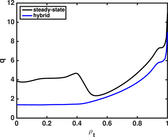
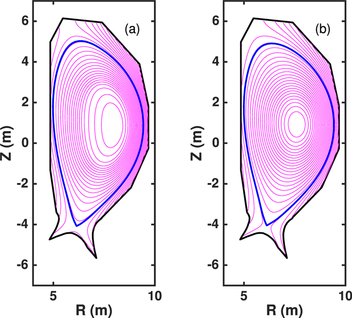
Figure 1 shows the magnetic configurations in the CFETR steady-state and hybrid scenarios. The directions of the plasma current and the equilibrium magnetic field are both counter-clockwise from the top view. It means that the magnetic drift of an alpha particle is in the upward direction. The minor radius is a = 2.2 m. The magnetic field and the major radius at the axis are and for the steady-state scenario, and and for the hybrid scenario. The plasma currents for the steady-state and hybrid scenarios are and , respectively. The safety factor profiles in the CFETR steady-state and hybrid scenarios are shown in figure 2. ρt is the square root of the normalized toroidal magnetic flux. We can see from figure 2 that the safety factor in the hybrid scenario is smaller than that in the steady-state scenario. The safety factors at the axis for the steady-state and hybrid scenarios are and , respectively. The safety factors at 95% of the poloidal magnetic flux are and , respectively.
Figure
1.
The magnetic configurations (magenta) in the CFETR steady-state (a) and hybrid (b) scenarios. The black lines denote the shape of the first wall and the blue lines denote the LCFS.
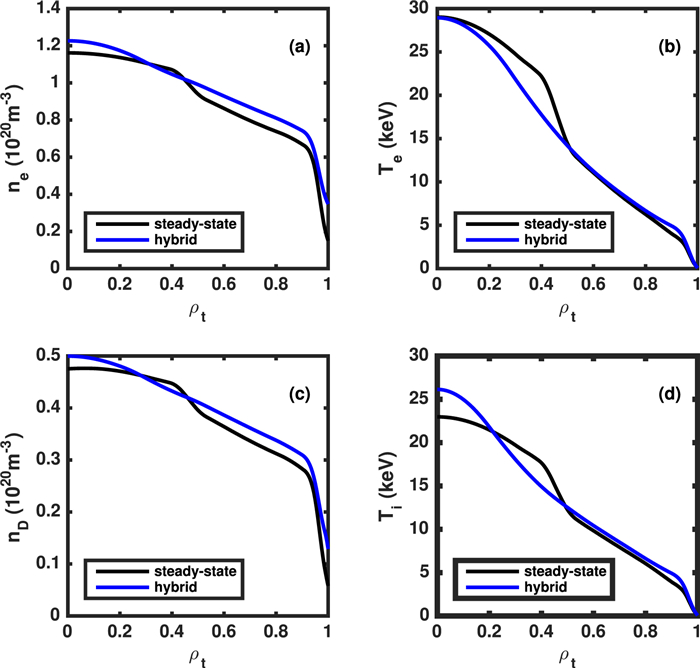
Figure 3 shows the density and temperature profiles, including the densities of electron and deuterium, and the temperatures of electron and bulk ion in the CFETR steady-state [32] and hybrid [33] scenarios. The tritium density profile is the same as the deuterium one. These profiles were obtained by integrated modeling described in [32, 33].
Figure
3.
The electron density (a) and temperature (b), and deuterium density (c) and ion temperature (d) profiles in the CFETR steady-state (black) and hybrid (blue) scenarios. The tritium density profile is the same as the deuterium one.
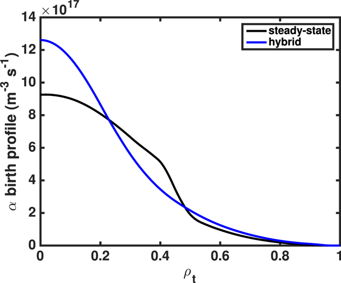
The source of fusion alpha particles is given by , which determines the birth distribution of alpha particles. Here, nD,T are the densities of deuterium and tritium, respectively. is the D-T fusion rate, which is given by for T ≤ 25 keV [34, 35]. Here, the unit of ion temperature T is keV. Using the density and temperature profiles and the equations above, we can compute the source or birth distribution profiles of alpha particles. Figure 4 shows the radial birth distributions of fusion alpha particles in the CFETR steady-state and hybrid scenarios. The energy of the initial alpha particles is Eα = 3.5 MeV.
Figure
4.
The radial birth distributions of fusion alpha particles in the CFETR steady-state (black) and hybrid (blue) scenarios.
The ripple parameter δ can be fitted with the following analytic function [11, 36]
(19)
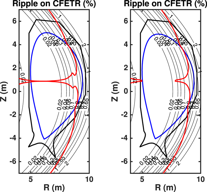
For the CFETR tokamak, the ripple-related coefficients are chosen as N = 16, δ0 = 1.57 × 10⁻⁵, Rrip = 6.01 - 0.062Z2, brip = 0.021, wrip = 0.63 m [18, 19]. The contour plots of the toroidal field ripple δ and the ripple well boundaries in the CFETR steady-state and hybrid scenarios are shown in figure 5. The ripple well regions are mainly located on the right side of the ripple well boundaries. The maximal ripples within the LCFS in the steady-state and hybrid scenarios are both about 0.4%. Both of the maximal ripple values are located at R = 9.4 m and Z = 1 m, that is, the top right of the LCFS. The ripple well boundary is determined by , where ϵ is the inverse aspect ratio and θ is the geometric poloidal angle.
Figure
5.
The contour lines (black) of the toroidal field ripple and the ripple well boundaries (red) in the CFETR steady-state (a) and hybrid (b) scenarios. The black bold lines denote the shape of the first wall and the blue lines denote the LCFS.
In all our alpha particle loss simulations, the Coulomb collision effect was included. The total simulation time is about 1.3 s, which is sufficient for an alpha particle slowing down and becoming a thermal ion. About 20 000 test particles were used for simulating loss fractions, loss regions and heat loads of alpha particles.
4.
Numerical results
The numerical results of the alpha particle loss in the CFETR tokamak with ripple and collision computed by the GYCAVA code are presented in this section.
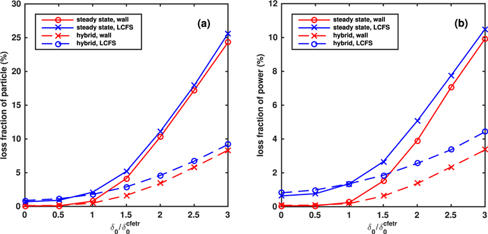
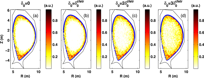
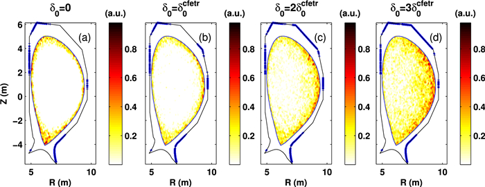
Figure 6 shows the relation between the particle and power losses of alpha particles and the ripple amplitude parameter δ0 in the CFETR steady-state and hybrid scenarios with the LCFS and wall boundaries. δ0 = 0 denotes the case that the ripple effect is not included. In the case without the ripple effect, the alpha particle loss is very small. It is because most of alpha particles are deposited in the core region and in this case the alpha particle loss is only due to the magnetic drift and collision. In the cases with the ripple effect, that is, δ0 ≠ 0, we can see from figure 6 that the ripple effect enhance the alpha particle loss. The loss fraction of alpha particles in the steady-state scenario is much larger than that in the hybrid scenario for , which is due to the fact that the safety factor in the steady-state scenario is larger than that in the hybrid scenario (see figure 2). According to Goldston et alʼs theory [31], the ripple stochastic diffusion is positively related to the safety factor. The loss fractions of alpha particles increase rapidly with δ0 increasing, especially for the steady-state scenario. The main ripple loss mechanisms are the ripple stochastic diffusion and the ripple well loss. In contrast to the cases with the LCFS boundary, the alpha particle loss fractions are smaller in the cases with the wall boundary, because the wall is outside the LCFS. The alpha particle loss fractions in the steady-state scenario are much larger than those in the hybrid scenario, especially for the large δ0. In the case of , the particle loss fractions of alpha particles loss are small (about 2%) in the two scenarios with the LCFS boundary. However, in the case of , the particle loss fraction is 17.9% in the steady-state scenario with the LCFS boundary, which is very closed to the previous numerical results of alpha ripple loss [19] computed by the ORBIT code. Their numerical results indicated that the particle loss fraction is 17% in the case of δ0 = 4 × 10⁻⁵ (see table 2 of reference [19]). Figure 7 shows birth distributions and final positions of lost alpha particles for different ripple amplitude parameters δ0 in the CFETR steady-state scenario with the LCFS boundary. We can see that the loss regions (initial positions of lost ions) of alpha particles are mainly at the edge of plasma. With δ0 increasing, the loss region of alpha particles becomes wider. Because the loss of alpha particles for δ0 = 0 is very small, that is, the first orbit loss is small, the loss of alpha particles is closely related to the ripple and Coulomb collision effects for δ0 ≠ 0. For , some alpha particles in the plasma core are lost due to the ripple stochastic loss. The final positions of lost alpha particles are mainly located at the LCFS above the mid-plane. Figure 8 shows birth distributions and final positions of lost alpha particles in the steady-state scenario with the wall boundary. We can see that the final positions of lost alpha particles are on the wall. The loss regions of alpha particles are similar to those with the LCFS boundary.
Figure
6.
The particle and power fractions of lost alpha particles as a function of the ripple amplitude parameter δ0 in the CFETR steady-state and hybrid scenarios with the LCFS and wall boundaries. Here, .
Figure
7.
Contours of birth distribution and final positions (blue) of lost alpha particles for different ripple amplitude parameters δ0 in the CFETR steady-state scenario with the LCFS boundary.
Figure
8.
Contours of birth distribution and final positions (blue) of lost alpha particles for different ripple amplitude parameters δ0 in the CFETR steady-state scenario with the wall boundary.
Alpha particle loss simulations in the hybrid scenario with different boundaries have also been performed. The results on birth distributions and final positions of lost alpha particles are similar to those in the steady-state scenario.
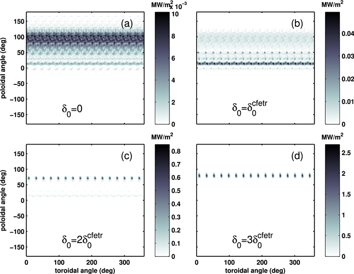
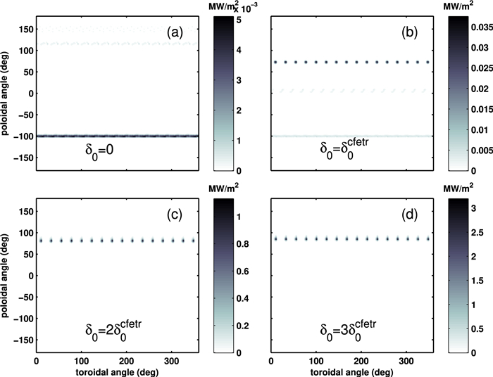
Figures 9 and 10 show the 2D distributions of heat loads induced by lost alpha particles for different ripple amplitude parameters δ0 in the CFETR steady-state scenario with the LCFS and wall boundaries, respectively. In the case with the LCFS boundary and without the ripple effect shown in figure 9(a), the heat loads of lost alpha particles are located on the LCFS above the mid-plane. However, in the case with the wall boundary and without the ripple effect shown in figure 10(a), heat loads of lost alpha particles are mainly located on the lower divertor. It is related to the fact that plasmas or the LCFS are more close to the lower divertor in contrast to the upper divertor. In the case with the LCFS boundary and shown in figure 9(b), most of heat loads of lost alpha particles are near the mid-plane, which is mainly induced by the ripple stochastic loss. In the case with larger δ0 shown in figures 9(c) and (d), we can see some localized heat loads at θ = 70°–80°. The number of heat load spots is 16, which is the same at the toroidal field coil number. In addition, the poloidal position of heat load agrees with the upward direction of the magnetic drift of an alpha particle. Therefore, these heat loads are induced by the ripple well loss.
Figure
9.
Heat loads induced by lost alpha particles for different ripple amplitude parameters δ0 in the CFETR steady-state scenario with the LCFS boundary.
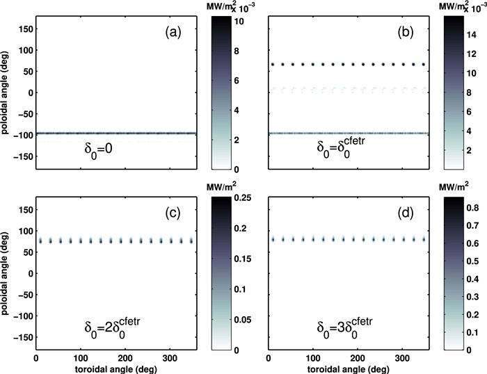
Figure
10.
Heat loads induced by lost alpha particles for different ripple amplitude parameters δ0 in the CFETR steady-state scenario with the wall boundary.
In the case with the wall boundary and shown in figure 10(b), we also can see 16 heat load spots at the position that the poloidal angle is θ ≃ 70°, which are different from the heat loads in the case with the LCFS boundary shown in figure 9(b). It means that the ripple well loss occurs outside the LCFS and makes the heat loads become localized. Comparing the heat loads in figure 10(b) with those in figure 9(b), we can obtain the result that losses of alpha particles are due to the combination effect of the ripple stochastic diffusion and the ripple well loss in the case with the wall boundary. The other evidence of this result is given by a typical orbit of a lost alpha particle shown in figure 12(c) below. In the cases with the wall boundary, the maximum value of the heat loads is about 0.035 MW m-2 for , but it is about 1 MW m-2 for .
Figure 11 shows the heat loads of lost alpha particles in the hybrid scenario with the wall boundary. The poloidal and toroidal distributions of heat loads shown in figure 11 are similar to those in the steady-state scenario shown in figure 10. The difference between the results of these two scenarios is that the heat loads in the hybrid scenario are much smaller than those in the steady-state scenario.
Figure
11.
Heat loads induced by lost alpha particles for different ripple amplitude parameters δ0 in the CFETR hybrid scenario with the wall boundary.
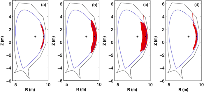
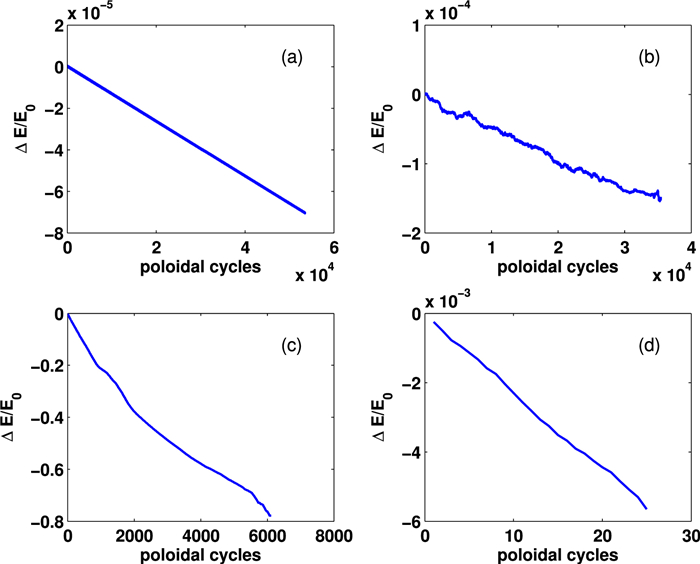
In order to well understand the 2D heat load distributions of lost alpha particles, typical orbits of lost alpha particles are studied and discussed below. Guiding-center orbits of trapped alpha particles in the CFETR steady-state scenario in the four cases are shown in figure 12. Four cases include the case without collision and ripple, the case without collision and in the presence of ripple (, the case with collision and ripple (), and the case with collision and ripple (). The corresponding ∆E/E0 (∆E = E - E0) evolutions of these alpha particles are shown in figure 13. These energetic alpha particles have the same initial phase space position. The initial energy of alpha particles is E0 = 3.5 MeV and the initial pitch is . In the case without collision and ripple shown in figure 12(a), we can see that the guiding-center orbit of alpha particle is an unperturbed banana orbit. In the case without collision and in the presence of ripple shown in figure 12(b), we can find that the ripple stochastic effect makes the alpha particle move radially and hit the first wall finally. The numerical error of the particle energy of alpha particle in the cases without collision, shown in figures 13(a) and (b), is on the order of 10-4. The simulation time shown in figure 13(a) is 1.3 s, that is, 5.4 × 10⁴ poloidal cycles for the trapped alpha particle. It means that the numerical energy conservation is accurate in our long-time simulation of the alpha particle orbit without the collision effect.
Figure
12.
Guiding-center orbits (red) of trapped alpha particles in the CFETR steady-state scenario and in the four cases: (a) the case without collision and ripple, (b) the case without collision and in the presence of ripple , (c) the case with collision and ripple , and (d) the case with collision and ripple . The plus symbol denotes the position of the magnetic axis and the cross symbol denotes the initial position of an alpha particle.
In the case with the collision and ripple shown in figure 12(c), it is found that the alpha particles move radially due to the ripple stochastic diffusion effect in the early stage and then move vertically upward due to the ripple well loss mechanism outside the LCFS. In the other words, the alpha particle loss is due to the ripple stochastic loss when the LCFS boundary is used, whereas the alpha particle loss is due to the ripple stochastic transport and the ripple well loss when the wall boundary is used. The radial position of the ripple well loss agrees with the analytic ripple well region shown in figure 5(a). The orbit shown in figure 12(c) is a typical orbit of a lost alpha particle in the CFETR magnetic configuration. The typical orbit can explain the heat loads of lost alpha particles with different outer boundaries shown in figures 9(b) and 10(b). By comparing the cases without and with collision shown in figures 12(b) and (c), we can find that the Coulomb collision effect plays an important role in the transition of the lost alpha particle behavior from the ripple stochastic diffusion to the ripple well trapping. In the cases with collision, the alpha particle energy decreases rapidly with time due to the collision-induced slowing down effect, which can be seen from figures 13(c) and (d).
As shown in figure 12(d), the alpha particle orbit in the case with has the similar behavior of that in the case with shown in figure 12(c). The transition from the ripple stochastic transport to the ripple well trapping occurs within the LCFS in contrast to the orbit shown in figure 12(c). It is because the larger ripple amplitude parameter δ0 has been used in the former case. These typical orbits can also explain the heat loads of lost alpha particles shown in figures 9(c) and 10(c). In addition, we can see from figures 13(c) and (d) that the alpha particle loss occurs more rapidly in the case with .
5.
Summary
Energetic alpha particle losses with the toroidal field ripple and the Coulomb collision have been numerically studied by the orbit-following code GYCAVA in the CFETR steady-state and hybrid scenarios. The effects of the outer boundary and the ripple amplitude on alpha particle losses have been investigated. The LCFS or the first wall has been used as the loss boundary for simulating loss fractions, loss regions and heat loads of alpha particles.
The loss fractions and heat loads of alpha particles in the hybrid scenario are much smaller than those in the steady-state scenario for a significant ripple amplitude δ0. The loss fraction of alpha particles increases rapidly and the loss region becomes wider with δ0 increasing. The loss of alpha particles is closely related to the ripple and Coulomb collision effects. The loss regions of alpha particles are mainly at the edge of plasma. Some alpha particles in the plasma core are lost due to the ripple stochastic transport for a large ripple amplitude δ0.
For the CFETR tokamak, heat loads with the LCFS boundary are mainly near the mid-plane, which is due to the ripple stochastic loss. However, heat loads with the wall boundary are localized and mainly located at the position that the poloidal angle is θ = 70°–80°. This position of heat load is related to the direction of the magnetic drift. Discrete heat load spots are due to the ripple well loss.
The heat loads of lost alpha particles with different outer boundaries can be explained by typical alpha particle orbits. The transition of the lost alpha particle behavior from the ripple stochastic diffusion to the ripple well trapping has been identified in the CFETR tokamak. The transition can occur inside or outside the LCFS, which is dependent of the ripple amplitude parameter δ0. The Coulomb collision effect is responsible for the transition from the ripple stochastic diffusion to the ripple well trapping.
Acknowledgments
The authors appreciate the support from the CFETR team. Numerical simulations were performed on the ShenMa High Performance Computing Cluster in Institute of Plasma Physics, Chinese Academy of Sciences. The work was jointly supported by National Natural Science Foundation of China (Nos. 12175034, 12005063), the National Key R&D Program of China (No. 2019YFE03030001) and the Fundamental Research Funds for the Central Universities (No. 2232022G-10).
Li, N., Xu, Y., Zhong, F. et al. Numerical study of alpha particle loss with toroidal field ripple based on CFETR steady-state scenario. Chinese Physics B, 2024, 33(1): 015202.
DOI:10.1088/1674-1056/ad03de
2.
Xu, Y., Wang, F., Li, Y. et al. Guiding-centre orbit-following simulations of charge exchange loss of NBI ions with the finite Larmor radius effect. Journal of Plasma Physics, 2023, 89(6): 2300118.
DOI:10.1017/S0022377823001186

 DownLoad: