School of Physics, Harbin Institute of Technology, Harbin 150000, People's Republic of China
2.
National Key Laboratory of Electromagnetic Environment (LEME), China Research Institute of Radio Wave Propagation, Qingdao 266107, People's Republic of China
3.
Heilongjiang Provincial Key Laboratory of Plasma Physics and Technology, Harbin 150000, People's Republic of China
In order to solve the thickness dependence of plasma absorption of electromagnetic waves and further reduce the backward radar scattering cross section (RCS) of the target, we designed a novel composite structure of a metasurface and plasma. A metasurface with three absorption peaks is designed by means of an equivalent circuit based on an electromagnetic resonance type metamaterial absorber. The reflection and absorption of the composite structure are numerically and experimentally verified. The finite integration method was used to simulate a composite structure of finite size to obtain the RCS. The experimental measurements of electromagnetic wave reflection were conducted by a vector network analyzer (Keysight N5234A) and horn antennas, etc. The research showed that the absorption capacity of this composite structure was substantially improved compared to either the plasma or the metasurface, and it is more convenient for application due to its low plasma thickness requirement and easy fabrication.
Plasma plays an essential role in electromagnetic wave stealth technology. The refraction of plasma to electromagnetic waves and the absorption of electromagnetic waves by particle collision provide the theoretical basis for plasma stealth. In the field of aerospace, information blocking caused by a spacecraft returning through the atmosphere has been observed. The term 'plasma stealth' was first introduced by Vidmar after years of research on the interaction between electromagnetic waves and plasma [1]. Meanwhile, many studies on plasma stealth have been undertaken recently by academics both domestically and internationally; the methods applied in the research include theoretical analysis, numerical simulations and experimental verification; for instance, the analysis of the scattering characteristics of plasma surrounding a two-dimensional airfoil, the calculation of the propagation of electromagnetic waves in a magnetized nonuniform collisional plasma, and the fabrication of a semi-elliptical plasma generator and the experimental study of its attenuation characteristics [2–4]. The theory is relatively mature from domestic and international research. However, the generation of large-area plasma is more difficult and it can only cover part of the location with high scattering intensity, which is still problematic in practical applications of large-area stealth.
Meanwhile, plasma stealth has a very strong dependence on the thickness of plasma. Howlade conducted attenuation experiments using a thin 0.3 mm thick plasma with an electron density of about 2.7×10¹⁸m−3, and the maximum attenuation was only 0.02 dB [5]. It has been found that plasma thickness in general needs to be up to a few hundred millimeters in order to decay the electromagnetic waves effectively, and high power is also required to produce a high density of electrons.
Therefore, in order to solve the thickness and power consumption problems, numerous researchers have added absorbing materials behind the plasma to strengthen attenuation [6]. Yuan et al studied the transmission of electromagnetic waves under the joint action of an absorbing material and plasma [7]. Bai et al investigated the transmission of absorbing materials and plasma composite structures during oblique incident electromagnetic waves [8]. However, the limited absorbing capacity of ordinary absorbing materials cannot effectively reduce the thickness of plasma. It is very important to find new absorbing materials. Hence, we turn our attention to metamaterials—another direction of electromagnetic stealth [9].
Metamaterials are composite materials formed by the arrangement and combination of aperiodic or periodic artificial microstructural units based on the application requirements. After more than 20 years of development, metamaterials have developed from left-handed materials, stealth cloaks, and composite left-handed transmission lines to the current coding metamaterials and phase gradient metamaterials. The earliest perfect absorbing metasurface was proposed by Landy et al [10], marking the emergence of a new material design concept, but the frequency band was narrow, and the polarization was sensitive. A multilayer tower structure was later designed to achieve the bandwidth extension [11], but the polarization problem still existed. Then it was found that the polarization insensitivity of wave absorption could be achieved by strong symmetry of the unitary structure [12]. In recent years, a technique was even developed to combine 3D printing with metamaterials [13], which provided a more convenient way to make 3D structures and expand the capability of metamaterials [14]. However, the attenuation peak position of the simple metasurface was fixed due to the limitations of the structure; the structural parameters are not easy to regulate, and it lacks enough flexibility to face the weakness of multi-band radar. The composite structure of plasma and metasurface can reduce the existence of problems such as thickness modulation, so it makes sense to combine it with plasma [15].
Based on the above-mentioned studies and problems, we combined plasma with a designed metasurface. Here, we analyzed the absorption structure through a simple equivalent circuit. We designed two novel composite structures to solve the above problem, and they were simulated and experimented. It was verified that our designed structures produce a large attenuation of reflected and backscattered electromagnetic waves with the advantage of simple plasma generation conditions and low thickness.
The paper is organized as follows. In the next section, the designed metasurface structure is described by means of an equivalent circuit and verified with simulations and experiments. In section 3, the wave absorption capacity of the two designed composite structures is tested and analyzed, and the results are compared with those when only the plasma or the metasurface is available. Finally, section 4 shows the effect of the finite-size structure on the backscattered radar cross section (RCS).
2.
Design of the metasurface
2.1
Structure of the metasurface and the principle of its design
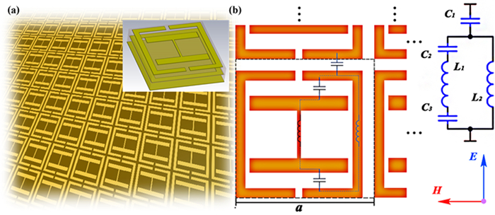
The metasurface is designed as a periodic structure with each cell as shown in figure 1(a) consisting of three layers of copper structure with two layers of FR-4 with a period of 5.7 mm, in which the thickness of copper is 0.034 mm and the thickness of FR-4 is 0.6 mm. As for the back side of the overall structure, which is the third copper layer, the entire area is covered with copper as the total reflective surface.
Figure
1.
Design of metasurface structures. (a) Overall configuration of the metasurface, and structure of the copper layer of each periodic cell. (b) Equivalent circuit of the surface structure (unit structure consists of an internal I-shaped structure and an external bezel) when the electric field of the incident electromagnetic wave is parallel to the central metal line.
This structure generates a coupled electric field in the direction parallel to the incident plane, and this coupled electric field can be equated to an electric dipole to produce an electric resonance. Under the action of the magnetic field the metal on both sides of the dielectric plate generates currents in opposite directions, so the accumulation of dissimilar charges at the same position on both sides generates displacement currents. The equivalent circuit can be equated to a magnetic dipole generating magnetic resonance. Through adjustment of the parameters, the equivalent permeability and dielectric constant are approximated at the resonant frequency, so that the structure matches the spatial impedance and the energy is gathered in the structure and lost to achieve the wave absorption effect.
When the direction of the electric field of the incident wave is parallel to the central copper line of the structure, the equivalent circuit is shown in figure 1(b). Its unit structure can be regarded as the LC resonance circuit of the serial–parallel capacitor and inductor [16]. The free electrons in adjacent metal wires parallel to the direction of the electric field move in the same direction under the action of the electric field to produce self-inductance. At the same time, anisotropic charges accumulate in the direction of the upper and lower surfaces of the metal, so displacement currents exist between adjacent thin metal layers in the direction of parallel electric fields. The displacement current and the conduction current in the metal together form an equivalent current loop [17, 18]. The metasurface structure produces three absorption peaks, and the position of the highest frequency peak can be changed by adjusting the sizes of L1,C2 and C3 without changing the overall structure. Changing C1 and L2 also changes the middle absorption peak, and the position of the lowest peak is controlled by the equivalent electromagnetic resonance of the last two layers of copper cladding. Eventually, after adjustment, the width of the metal line at the center of the unit structure is set to 0.15 mm, the width of the surrounding class border structure is 0.4 mm, and the distance between the I-shaped structure and the upper and lower borders is 0.65 mm.
2.2
Simulation and experimental validation
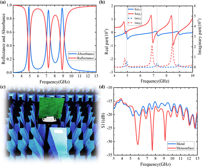
In order to verify the designed structure, we use CST (CST Studio Suite) to simulate it. In our simulation, the plasma is treated as a homogeneous medium whose dielectric constant varies with frequency, while the metasurface structure is calculated as a complex structure in the simulation and cannot be used as a homogeneous medium of a certain thickness, which is determined by the properties of each part of the material as well as the boundary conditions, and is solved according to a system of Maxwell equations. Therefore, the created model needs to be meshed into a discrete structure recognizable by the software; in this case we use the finite element method and choose a tetrahedral mesh for its division. The accuracy of the simulation mainly depends on the degree of discrete structure, so the accuracy can be improved by increasing the number of meshes, but an overly dense mesh division will result in a very much increased computation time, so a reasonable 'cell per max model box edge' parameter is needed to adjust the size of the mesh. The waveguide port parallel to the coppers simulates the propagation of electromagnetic waves in the medium, and scattering parameters related to frequency are obtained. The order of magnitude of S21 (transmission coefficient) is 10−3, so the transmittance T(ω) can be approximately 0, which is consistent with the total reflection designed by the structure. According to A(ω)=1−R(ω)−T(ω) [19], the absorption rate can be calculated as shown in figure 2(a). It can be seen that the structure has three effective absorption peaks at 4.8 GHz, 7.3 GHz, and 9 GHz, respectively, and the maximum absorption rate can reach 99%.
Figure
2.
Simulation and experimental results of the metasurface. (a) Simulation results of the metasurface, where the red line represents the reflectivity and the blue line represents the absorbance. (b) Blue and red lines indicate the equivalent relative permittivity and permeability of the overall structure, with the solid and dashed lines indicating the real and imaginary parts of the two parameters, respectively. (c) Reflection experiments on the metasurface by the vector network analyzer and horn antenna in an environment covered with absorbing sponge. (d) S11 (reflection coefficient); the red line shows the experimental results of the attenuation of electromagnetic wave reflection by the metasurface and is compared with the metal plate indicated by the blue line.
When the relative equivalent permeability and dielectric constant are negative, the refractive index is still positive, so electromagnetic waves can still be propagated in it, and the wave just cannot propagate in the material with a single negative value. To achieve wave absorption, the first consideration is to make the reflection small enough. That is, the impedance of the material and the air impedance need to match each other; the impedance of the material is
Z(ω)=√μr(ω)εr(ω).
(1)
It can be seen that when the real part of the effective permittivity εr and the effective permeability μr are equal, the structure can be matched with the spatial impedance. In addition, it is necessary to concentrate energy in the structure to achieve the effect of absorbing waves. Therefore, the structure needs to have high electromagnetic losses, that is, the structure needs to have a large imaginary value of permittivity or permeability. From figure 2(b), we can see that the three frequencies corresponding to the above matching and attenuation characteristics are basically the same as the positions of the three absorption peaks in figure 2(a).
In order to verify whether the experimental results of the structure are consistent with the theoretical simulation, we fabricated the metasurface by making a printed circuit board (PCB). First, copper was coated on both sides of 0.6 mm thick resin, and then dry film was affixed and exposed to ultraviolet light at the complementary position of the designed figure. Then a developer was used to remove the unexposed part of the dry film, and tin plating was used to remove the exposed part of the dry film. The copper and tin were etched off respectively, and the copper coating pattern was finally left. The designed metasurface structure was completed by gluing the finished plate to another plate which was copper-coated directly on one side of the resin plate.
The effect of the fabricated structure on electromagnetic wave propagation was measured using a vector network analyzer and a horn antenna, and the effect of a metal plate in free space on electromagnetic waves was used as a reference result. The experimental device is shown in figure 2(c), where a vector network analyzer is used to transmit electromagnetic waves to the metasurface in an environment covered with absorbing sponges and measure the loss of reflected waves [20, 21].
When measuring the reflection of the metal plate, the time domain gate was opened to reduce the influence of reflection of surrounding objects. The results are shown in figure 2(d), with obvious electromagnetic attenuation within the range of 5‒10 GHz. It can be seen that the three clear peak values of 5.9 GHz, 7.7 GHz and 9.1 GHz correspond to the simulation results. However, the position has a slight frequency shift, which can be attributed to the approximate processing of the model in the simulation and the thickness change caused by the gap between the two PCB boards. The degree of attenuation at other locations is essentially the same as that of the metal plate.
3.
Plasma and metasurface composite structures
3.1
Simulation and experimentation of structures formed by the combination of cylindrical plasma and metasurface
When the frequency of the incident electromagnetic wave entering the plasma is higher than the cutoff frequency of the plasma, the electric field does work to the electrons in the plasma, resulting in a reduction in the electric field energy [22, 23]. The energy of the electrons is converted into internal energy in the collision [24, 25]. For plasma, the main influence factors are collision frequency and plasma frequency [26]. The plasma frequency can be expressed as
ωpe=√nee2ε0me,
(2)
where ε0 represents the dielectric constant in a vacuum, e,me are the electric charge and mass of electrons, respectively, and ne denotes the free electron density of the plasma.
Considering the application conditions that require plasma generation conditions to be as simple as possible, discharge tubes were used as its generation device i.e. cylindrical plasma. Moreover, in addition to collision absorption, the columnar plasma also enables electromagnetic wave scattering to further reduce reflections [27, 28]. Hence, the design is made by placing several mutually parallel cylindrical plasmas in the plane where the hyperplane is located. The radius of one of the cylindrical plasmas is 3.5 mm and the distance between each plasma column is 18 mm. The distance between the center of the plasma and the metasurface is 4 mm. The Debye radius of the plasma is
λDe=(ε0Teen0)12,
(3)
where Te is the electron temperature. In the space scale of the equivalent circuit of the metasurface, the plasma is electrically neutral. It does not affect the effect of the electromagnetic resonator, so the plasma and the metasurface are very suitable for combining to absorb electromagnetic waves.
The plasma is generated by commercial fluorescent lamps with a mixture of argon and mercury inside the discharge tube at a pressure of 3–15 Torr. The driving source is a CTP-2000 K high-voltage AC power supply with adjustable voltage in the range of 8–50 kHz. Liu and Hou have measured the characteristic frequencies ωpe of the plasma it produces and the collision frequency υ experimentally [29]. According to the diagnostic results, the plasma frequency is 16–42 Grad s–1, while the collision frequency is between 20 GHz and 70 GHz.
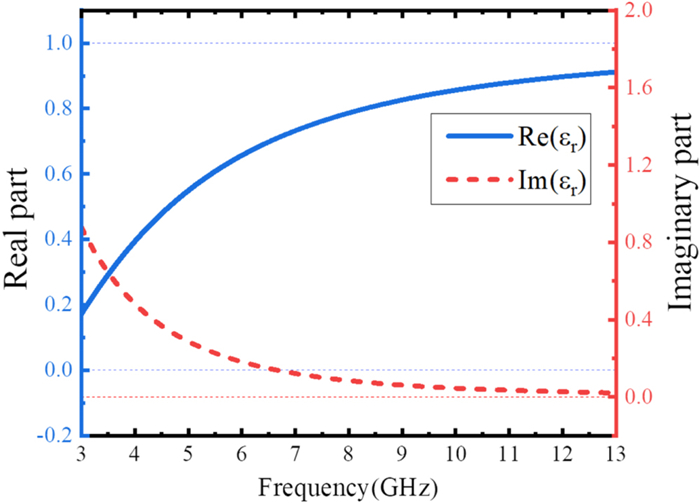
Therefore, we used ωpe=25Grads−1,υ=20GHz as the plasma parameters for the simulation, and constructed the designed model in CST. Under the Drude model, considering the effect of collisions, the relative permittivity εr of the plasma is expressed as
εr=1−ω2pe(ω2+ν2)−jνω2peω(ω2+ν2),
(4)
where ω is the frequency of the incident electromagnetic wave. The real and imaginary parts of the curve of the above equation are shown in figure 3.
Figure
3.
Relative dielectric constant of plasma (plasma frequency is 25 Grad s–1 and collision frequency is 20 GHz).
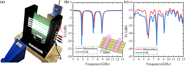
In this regard, we added a row of discharge tubes in front of the above experimental structure as the next step of the composite structure experimental device, as shown in figure 4(a). We call this composite structure P-M, which is a combination of a columnar plasma and metasurface. When electromagnetic waves propagate in this composite structure, they first pass through the plasma layer, where the energy decays under the collisional absorption of the plasma. At the same time, scattering occurs to further reduce the energy of the electromagnetic waves incident to the metasurface. Due to the impedance matching of the surface, most of the electromagnetic wave energy enters the inner part of the metasurface, which is further lost and then enters the plasma layer together with a small number of reflected waves from the surface. Again the plasma absorbs and scatters, and finally the electromagnetic waves return to the monitor after multiple attenuation. The P-M results were compared with the results when only the metasurface was available. From the simulation results in figure 4(b), it can be seen that the addition of the plasma column does not affect the induced electric potential and induced magnetic field generated by the metal structure in the metasurface in the alternating electromagnetic field, and the metasurface structure can still generate electromagnetic resonance and thus lose electromagnetic wave energy, so there are still three effective absorption peaks. The plasma column only enhances the attenuation ability at the absorption peak, and makes the other frequency bands receive a small frequency shift. To verify the correctness of the results, the results were compared by measuring whether the attenuation of the reflected wave under excitation was obtained. According to figure 4(c), additional attenuation was 2–3 dB, especially at the peak values of 7.4 GHz and 9.1 GHz. The slight decrease in attenuation at 5.8 GHz can be attributed to the reflection from the wall of the discharge tube and the slight frequency shift to the lower band at the same time. Comparing the two results, it can be seen that the experimental results are in good agreement with the theoretical values. Since we chose a periodic and infinite size unit cell as the boundary condition in the simulation calculation of S-parameters in CST, and the size of the waveguide port is also infinite, it can absorb all reflected and scattered waves. In the experiment, only reflected waves and backscattered waves were received, while electromagnetic waves scattered in other directions by the columnar plasma could not be received. Therefore, in the experiment, the scattering effect of the columnar plasma on the electromagnetic wave was more obvious under finite size, and the attenuation ability of the low-frequency non-peak part was greatly enhanced compared with the simulation.
Figure
4.
Simulation and experimental results of composite P-M structures combining cylindrical plasma and metasurface. (a) Columnar plasma is generated using discharge tubes and placed in front of the metasurface, and experiments are carried out. (b) Attenuation results of the reflected waves from the P-M in the simulation; the inset shows the schematic of the periodic structure, where the column plasma diameter is 7 mm. (c) The blue line shows the experimental results of the composite structure, and the red line of the metal plate reflection is a control group.
This structure can achieve broadband absorption of at least −10 dB with a peak of about −30 dB in experiments using only a discharge tube with a radius of 4 mm and a wall thickness of 0.5 mm, which greatly reduces the energy consumption required to generate plasma and is more convenient for large-scale applications. At the same time, the longitudinal space required is significantly reduced compared to the more than 10 cm thick plasma required for single plasma stealth, which is more conducive to the application.
3.2
Effect of thin plasma thickness and air gap on electromagnetic wave absorption in composite structures
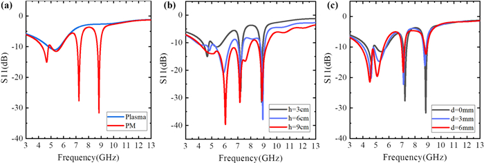
In addition to this scheme, we also designed a structure that directly adds a uniform thick plasma layer to the metasurface. The structure of the plasma is simple and easy to adjust. The bottom layer is the metasurface, the middle layer is the air gap, and the upper layer is the plasma layer. We call this composite structure P-M. The gap d between the plasma and metasurface and the thickness h of plasma were set as 0 mm and 3 cm, respectively, to simulate in CST and compare with that when only plasma was present. It can be seen from figure 5(a) that the structure attenuates significantly from 4 to 10 GHz, and the attenuation is mainly concentrated in the low-frequency part. The gentle part is about −5 dB on average, which is three more peaks than that in the environment with only plasma. Compared with the results when only the metasurface is available in figure 4(b), it is found that there is one more peak at 5.5 GHz than in the case of only the metasurface, and the attenuation of the two peaks at 7.9 GHz and 9 GHz increases by about −15 dB to reach −30 dB. Meanwhile, the frequency shift of the three peaks is about 0.1 GHz in the low-frequency direction. It can be seen that the composite structure has better wave absorption ability, and the thin layer of plasma does not affect the electromagnetic resonance ability of the metasurface structure under the action of electromagnetic waves.
Figure
5.
Simulation results of composite P-M structures combining metasurface and thin plasma with different parameters. (a) Simulation comparison of reflected wave attenuation for the P-M (red line) and when there is only plasma (blue line). (b) Simulation comparison of the PM with varying thin plasma thickness h at air gap d=0 mm. (c) Simulation results for varying the air gap size d between the plasma and the metasurface for a fixed plasma thickness h=3 cm.
In order to study the effect of the structure of the plasma we changed the thickness h of the plasma to 3, 6, and 9 cm. From figure 5(b), it can be seen that as the thickness of the plasma increases, the distance that electromagnetic waves travel in it grows and the energy it absorbs by collisions increases. This results in an increased ability of the composite structure to attenuate electromagnetic waves over the entire frequency range. The attenuation is concentrated in the low-frequency part regardless of how the thickness changes, and when the thickness reaches 9 cm, the attenuation of the low-frequency part can even reach −15 dB which is not the peak point of the absorption. The peak at 4.8 GHz does not change greatly with the change in thickness and gradually disappears due to the enhancement of the overall attenuation. However, the peak originally at 5.5 GHz moves in the high-frequency direction while being greatly enhanced and attenuated, increasing from −10 to −40 dB and moving about 0.5 GHz. The latter two main peaks move slightly in the low-frequency direction and are above −30 dB.
Based on the above results, we can find the importance of thickness for plasma stealth. It is a very feasible method to reduce the dependence on plasma thickness by coupling the designed metasurface with plasma, and the thickness required by plasma can be greatly reduced by using our designed structure.
To study the coupling effect between the plasma and metasurface, we fixed the thickness h of plasma layer as 3 cm and changed the distance d of the air gap to 0, 3, and 6 mm respectively to observe the attenuation of reflected wave. In figure 5(c), it can be seen that the overall attenuation of 3–10 GHz is enhanced with increasing gap thickness. The peaks of the two low-frequency bands at 4.8 GHz and 5.5 GHz are significantly enhanced as high as −5 dB to −10 dB with the increase of the gap, and move about 0.5 GHz. However, the two peaks at 7.2 GHz and 8.9 GHz show the opposite phenomenon, and their reflection of electromagnetic waves is increased, which can be attributed to the different interference effects caused by different wavelengths.
Based on the above analysis, we found that the attenuation capability of different frequencies can be changed according to the gap width, that is, we can regulate the absorbing capacity of the structure by adjusting the position of the plasma layer. In order to achieve the adjustable absorbing ability, pure plasma needs to change the distribution of different characteristic frequencies, and a pure metasurface needs to be designed with an adjustable structure. Both methods are too difficult to achieve, and the structure designed in this paper can accomplish this goal effectively.
4.
Analysis of backward RCS under finite size structure
In order to verify the effect of the designed structure on the backward RCS when the size is limited, its scattering characteristics were studied by finite difference time domain [30]. Simulation data for the composite structure of the combination of the metasurface and thin plasma are shown in figure 6.
Figure
6.
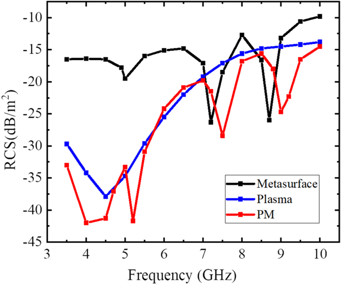
Backscattering cross section of the plasma, metasurface and composite P-M structure at finite size.
The results show that the metasurface has a significant attenuation ability to the backward RCS. Since the two copper-clad interlayers on the rear side of the experiment are no longer uniform media and the spacing changes with the intervention of air, the joint action of the two eventually changes the equivalent capacitance constituted by the metal wires on both sides, causing the structure to change its magnetic resonance under alternating magnetic fields, and thus changing its resonant frequency. Therefore, even with the same finite size structure as in the experiment, the metasurface simulation results in figure 6 still show a frequency shift with respect to figure 2(d). In the simulation of the backward RCS, the spatial scale of the finite size structure is smaller than the wavelength, resulting in a larger share of diffraction in the propagation of electromagnetic waves. Therefore, the backward RCS curve is only an analysis of the maximum side flap value in the wave flap map, and diffraction will result in a different frequency at the peak than at total reflection. At a certain obstacle size, the longer the wavelength, the larger the cross-sectional area of the first Fresnel ellipsoid in which the wave propagates. A large cross-sectional area will result in a smaller relative blocking area, and thus trigger a stronger field at the reception. Concluding from the above, the lower the frequency, the stronger the diffraction capability. Hence, the structure has a greater effect on the backscattered RCS at lower frequencies of electromagnetic waves. Meanwhile, the backscattering attenuation peak of the finite size structure is basically consistent with the frequency of the reflection wave attenuation peak under the infinite plane above, which indicates that the designed structural unit can still form an effective electromagnetic resonator for electromagnetic wave absorption loss when the number of structural units is limited. The backscattering RCS under the action of pure plasma is also significantly reduced, especially in the low-frequency range from 4 to 6 GHz, because the thin layer of plasma with limited lateral size has a significant scattering effect on electromagnetic waves.
Compared with the pure metasurface, the composite structure of thin-layer plasma and metasurface has stronger attenuation in the low-frequency range, and the lower the frequency, the greater the attenuation. In the range of 4–10 GHz, the attenuation can reach more than −15 dB and even reach −40 dB. For the plasma, the smaller the lateral size, the stronger the scattering effect on electromagnetic waves, so the attenuation ability is generally enhanced compared to the results in figure 5(a). For the metasurface, the larger the size, the stronger the electromagnetic resonance effect, so the attenuation effect of plasma on electromagnetic waves is enhanced with the decrease of size when the composite structure has limited space size. In the low-frequency part, due to the strong diffraction ability of electromagnetic waves, the attenuation ability of the composite structure to electromagnetic waves under the effect of diffraction and scattering is greatly enhanced, while the high-frequency part of the role of the two is not enough to compensate for the reduction of the electromagnetic resonance effect, and the attenuation ability is slightly weakened. Thus, the attenuation capacity of the high-frequency part of the P-M structure becomes smaller compared to that of figure 5(a), while the attenuation capacity of the low-frequency part becomes larger.
The above results show that the composite structure can effectively reduce the backscattered RCS. Moreover, the finite size structure has good attenuation characteristics compared to the infinite plane under the scattering effect of thin plasma, which indicates that the structure is more effective in reducing the energy of reflected and backscattered electromagnetic waves to enhance the electromagnetic stealth capability under radar in practical applications.
5.
Conclusion
In this work, we designed a novel type of composite structure based on the principle of electromagnetic resonance in order to improve the wave absorption capacity to reduce the backscattering RCS. This type of structure is composed of plasma and metasurface, and for the structure of plasma, two types of plasma are studied in the paper: column plasma and thin layer plasma. For the P-M structure, the scattering effect of the column plasma can significantly reduce the reflection in the low-frequency range under the limited size. Meanwhile, the discharge tube used to generate the column plasma has the advantages of simple generation, low energy consumption and easy disassembly, which can be used for maritime and land stealth. The P-M structure, on the other hand, makes the laminar plasma free from the thickness limitation by the action of the metasurface. Only 3 cm is required to allow the attenuation of electromagnetic waves to reach −10 dB in the low frequency range and even −30 dB at the peak. Then, the positive correlation between the absorption capacity and thickness in addition to the effect of air gap on the absorption frequency was verified by comparing the attenuation of electromagnetic waves with different thicknesses of plasma and different air gap sizes. Compared with the complicated means to change the absorption band when only the plasma or metasurface is available, the P-M structure makes it simpler to change the size of the air gap and is more flexible in practical applications. Finally, the electromagnetic stealth capability of the structure and the scattering effect of the thin layer of plasma in it are verified by the effect of the finite size composite structure on the RCS. In general, the composite structure not only absorbs electromagnetic waves and reduces the backward RCS but also has the advantages of low thickness and easy adjustment.
Acknowledgments
The research has been financially supported by National Natural Science Foundation of China (No. 12175050) and the Foundation of National Key Laboratory of Electromagnetic Environment of China (No. 202101003).
Howlader M, Yang Y Q and Roth J R 2002 Time-averaged
electron number density measurement of a one atmosphere
uniform glow discharge plasma (OAUDGP) by absorption
of microwave radiation Proc. of 2002 IEEE Int. Conf. on
Plasma Science (Banff) (IEEE) 271
Guo, S., Dong, G., Chen, J. et al. Plasma and metasurface composite absorber based on topology optimization. Journal of Physics D: Applied Physics, 2024, 57(45): 455208.
DOI:10.1088/1361-6463/ad6d7c
2.
Zhao, Z., Li, X., Dong, G. et al. Wideband radar cross-section reduction by a double-layer-plasma-based metasurface. Plasma Science and Technology, 2024, 26(6): 065503.
DOI:10.1088/2058-6272/ad2c3e
3.
Chen, G., Zhang, T., Wang, Y. Bridging Mechanisms Between Micro and Macro. Electromagnetic Wave Absorbing Materials: Fundamentals and Applications, 2024.
DOI:10.1002/9781119699316.ch5
4.
Zhou, Y., Hao, Z., Yuan, C. et al. Microhollow Cathode Plasma Studies and Effect of Array Structure on Electromagnetic Wave Propagation. 2024.
DOI:10.1109/PIERS62282.2024.10617848
5.
Magarotto, M., Sadeghikia, F., Schenato, L. et al. Plasma Antennas: A Comprehensive Review. IEEE Access, 2024.
DOI:10.1109/ACCESS.2024.3411142

 DownLoad: