Figure
1.
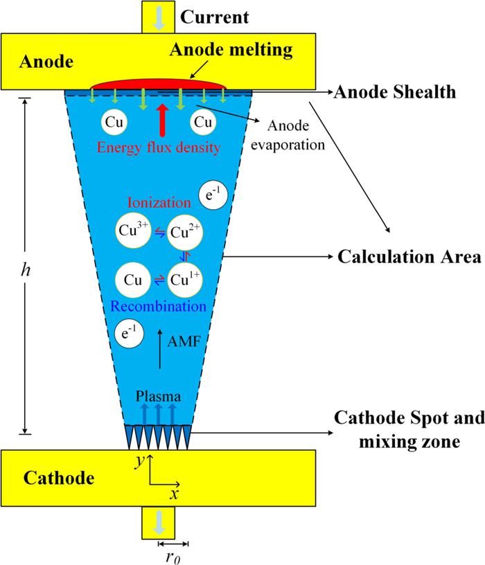
Physical model.
| Citation: |
Zhefeng ZHANG, Lijun WANG, Ze YANG, Ming LUO, Jiagang LI. Numerical simulation of low-current vacuum arc jet considering anode evaporation in different axial magnetic fields[J]. Plasma Science and Technology, 2022, 24(4): 044002. DOI: 10.1088/2058-6272/ac3903

|
As the main source of the vacuum arc plasma, cathode spots (CSs) play an important role on the behaviors of the vacuum arc. Their characteristics are affected by many factors, especially by the magnetic field. In this paper, the characteristics of the plasma jet from a single CS in vacuum arc under external axial magnetic field (AMF) are studied. A multi-species magneto-hydro-dynamic (MHD) model is established to describe the vacuum arc. The anode temperature is calculated by the anode activity model based on the energy flux obtained from the MHD model. The simulation results indicate that the external AMF has a significant effect on the characteristic of the plasma jet. When the external AMF is high enough, a bright spot appears on the anode surface. This is because with a higher AMF, the contraction of the diffused arc becomes more obvious, leading to a higher energy flux to the anode and thus a higher anode temperature. Then more secondary plasma can be generated near the anode, and the brightness of the 'anode spot'increases. During this process, the arc appearance gradually changes from a cone to a dumbbell shape. In this condition, the arc is in the diffuse mode. The appearance of the plasma jet calculated in the model is consistent with the experimental results.
In the vacuum interrupters, different structures of contacts are used to generate different magnetic field distributions [1]. AMF contacts can significantly improve the performance of vacuum interrupters. When the high current vacuum arc (HCVA) is affected by different AMF distributions, it will show different modes [2, 3]. HCVA will present a multi-cathode-spot mode with an AMF higher than 10 mT kA-1. In this case [3], each plasma jet generated by a group of cathode spots seems to be independent. This is because AMF avoids the mutual attraction between each plasma jet due to Lorentz force. Therefore, in order to have a better understanding of the mechanism of HVCA, it is very important to study the characteristics of the individual plasma jet.
The low-current vacuum arc (LCVA) under different magnetic field distributions with short gap distance has been studied experimentally [4–6]. The results showed that the secondary plasma near the anode had a significant effect on the LCVA plasma jet. Popov et al conducted experiments on anode jets with the electrodes made of pure Cu and Cu–Cr alloy. They believed that anode evaporation was the main reason for the formation of secondary plasmas. When the anode vapor pressure was higher and the arc column plasma density was lower, anode evaporation was easier to generate [7]. Although the current of LCVA was low (60–120 A), the heating effect on the anode surface was significant because a single plasma jet was concentrated in the local small space. Boxman et al deduced the formula of the energy flux density injected into the anode, in which electrons and ions were the carriers of the energy [8]. With this formula, Wang et al obtained a range of peak energy flux density from 4.5×10⁸ to 1.4×10⁹ W m-2 [9]. In this work, the main concern is the anode activity within 10 ms, since the parameters of the vacuum arc under the first half-wave (10 ms) directly can determine the success of the interruption. The anode activity will be very obvious because the time of heating is very short and the heat diffusion is limited. As the anode temperature rises, the saturated vapor pressure of the anode evaporation will increase exponentially, and the anode will evaporate a large number of atoms, namely secondary plasma.
In the previous work, it was generally assumed that the proportion of the arc components was fixed, so the average charge of the plasma was also fixed in the entire calculation area [1]. However, the influences of different species of the arc components were not considered. In the later research, the researchers introduced the component transmission equation in the study of the arc [10]. Studies have shown that there are ions and atoms in the vacuum arc, and the charge state of the ions is not uniformly distributed in the plasma region.
At present, various numerical simulation methods have been used to conduct in-depth research on LCVA and HCVA plasma, such as the PIC method, the MHD method, and the hybrid method of PIC and MHD [11–15]. The MHD method is the most widely used method because the PIC method and the hybrid method require a great amount of calculation [12, 15]. In the vacuum arc research, the MHD method is a main way to study the influence of the secondary plasma generated by the anode evaporation on the vacuum arc [14]. This method uses the generalized Ohm's law to couple the fluid equation with Maxwell's equation, which can effectively describe the physical properties of the plasma. In this work, this kind of method is used to simulate the plasma jet.
The present work is devoted to the study with the help of numerical modeling of the following problem: whether the anode atom evaporation is able to explain the experimentally observed properties of LCVA plasma in strong AMF. The anode activity simulation and the plasma jet simulation are coupled to study the influence of anode atom evaporation on the plasma jet characteristics.
In order to study the influence of the generation of the secondary plasma near the anode on the plasma jet, a model is established to simulate the anode activity process and the generation of atomic vapor in this work. As shown in figure 1, the physical model is divided into two parts. In the part of the anode, in order to comply with the experimental conditions, the anode is considered to be a flat contact with a radius of 25 mm and a thickness of 4 mm [5]. In this part, the anode activity model is used to obtain the anode temperature by calculating the temperature rise caused by the energy flow of the plasma injected into the anode [15]. The simulation conditions are set according to the experiment [5], where the plasma jet is in the diffuse mode: the cathode radius is 1 mm, the anode radius is 2.5 mm, the gap distance is 8 mm, the total arc current is 60 A, and the quasi-steady solution of AMF is in the range of 30–150 mT. The model for the anode is coupled with the simulation of the vacuum arc.
The vacuum arc plasma jet is simulated by the MHD model and the component transmission model. The plasma region also considers copper ions in various ionization levels and copper atoms by the ionization and recombination process. In addition, the anode sheath is also considered [12].
In the vacuum arc jet experiments, the anode has a significant temperature rise because it is heated by the vacuum arc continuously. The saturated vapor pressure will increase exponentially with the temperature.
According to the different physical conditions of the cathode spots, the jet angle is generally considered to be 5°–30° [16, 17]. Therefore, in this work the jet emission angle is set as 15° (as shown in the figure 1, it is the angle between the line from the center of the cathode to the boundary of the anode and the cathode). The upper and lower contacts represent anode and cathode respectively, which are both made of Cu. The parameters of plasma emitted at cathode point are as follows: ion velocity is 104 m s-1, electron temperature is 3 eV, and ion temperature is 0.5 eV. The initial charge composition of copper is 28% Cu1+, 54% Cu2+ and 18% Cu3+. At the same time, it is believed that the cathode spot will also evaporate atoms, the density of which is assumed to be 10% of ion erosion [18].
The lateral boundary is considered as a free boundary, and the velocity of the ions should be parallel to the tangent direction of the free boundary. Due to the diffusion phenomenon of the plasma jet, the free boundary is generally not a straight line. Nevertheless, with the increase of the AMF, the Lorentz force due to the rotation current is sufficient to limit the diffusion caused by the pressure gradient [5]. Therefore, in order to simplify the calculation, the free boundary is considered as a straight line in this work. In addition, Ampere circuital theorem is used to give the boundary conditions corresponding to the current.
In the simulation, atoms and ions are controlled by different governing equations. Atoms are mainly controlled by fluid equations, and ions are controlled by magnetic fluid equations.
The simulation method used in this work is based on the 2D steady MHD model, which has been introduced in the previous works [1, 19]. Besides, the component transmission equations are given considering the ionization and recombination processes [10, 19, 20–22].
| ∇·(nCu1⃗ui)=˙nCu0-˙nCu1, | (1) |
| ∇·(nCu2⃗ui)=˙nCu1-˙nCu2, | (2) |
| ∇·(nCu3⃗ui)=˙nCu2, | (3) |
| ∇·(nCu0⃗ui)=-˙nCu0, | (4) |
| ˙nCuj=αCujnCujne-βCujnCu(j+1)n2e. | (5) |
When the subscript j is 0, it represents atoms, whereas otherwise it represents j-charged ions. For example, nCuj means the number density of Cu atoms when j=0, and the number density of j-charged Cu ions when j=1, 2, and 3. The explanations of the other parameters are shown in table 1, where the subscript s can be i, e, and a representing ions, electrons, and atoms, respectively.
| Symbol | Meaning |
| ns | Total number density of species s |
| e | Unit charge |
| Ionization rate | |
| Current density | |
| Ts | Average temperature of species s |
| zi | Average ion charge number |
| Average velocity of species s | |
| κ | Specific heat ratio |
| ∆H | Latent heat |
| r | Sensible enthalpy |
| σ | Electric conductivity |
| WCuj | Ionization energy |
| νei | Collision frequency between electrons and ions |
| μ0 | Vacuum permeability |
| αCuj | Ionization rate coefficient |
| βCuj | Recombination rate coefficient |
| C | Constant (C=2.6×10⁻²¹ m2·eV-1) |
| WH | Ionization energy of hydrogen |
| λs | Average thermal conductivity of species |
| M | Mach number |
| Hm | Enthalpy value |
 DownLoad:
CSV
DownLoad:
CSV
The relationships among different components are given by
| ne=nCu1+2nCu2+3nCu3, | (6) |
| ni=nCu1+nCu2+nCu3, | (7) |
| nCu=nCu0+nCu1+nCu2+nCu3, | (8) |
| na=nCu0, | (9) |
| zi=neni. | (10) |
In the momentum conservation equations and the energy conservation equations, the effects of the ionization and recombination processes are also considered [23].
| ∇·(mina⃗ua⃗ua)=-∇pa-mi(αCu0nCu0)ne⃗ua+mi(βCu0nCu1)n2e⃗ui, | (11) |
| ∇·((32nakTa+12mina⃗ua⃗ua)⃗ua)+∇·(pa⃗ua)=-32k(αCu0nCu0neTa-βCu0nCu1n2eTi), | (12) |
| ∇·(mini⃗ui⃗ui)=-∇(pi+pe)+→J×→B+miαCu0nCu0ne⃗ua-miβCu0nCu1n2e⃗ui. | (13) |
It is clear that when the atom density is low, the ion velocity is mainly decided by pressure gradients and Lorentz force. The ion energy conservation equation is written as
| ∇·((32nikTi+12mini⃗ui⃗ui)⃗ui)+∇·(-λi∇Ti)+∇·(pi⃗ui)=3memineveik(Te-Ti)+zieni⃗ui·→E+32k(αCu0nCu0neTa-βCu0nCu1n2eTi). | (14) |
In addition, the magnetic field is calculated by the magnetic transport equation, while the electric field is obtained by generalized Ohm's law like in [10].
In the previous work, the electron temperature mainly depends on joule heating [1, 19]. Considering the energy loss by the ionization process, the energy conservation equation for electrons is given by
| ∇·(32nekTe⃗ue)+∇·(-λe∇Te)=→J2σ-3∑j=0WCuj˙nCuj-3memineveik(Te-Ti). | (15) |
The ions, atoms, and electrons are regarded as ideal gas, which means the state equations of them are given by the ideal-gas equation.
Since the atoms are non-conductive, with the presence of atoms, the electric conductivity will be lower, which will affect the current density distribution. The electric conductivity is given as in [24].
The boundary conditions in the simulation are similar to our previous works [25]. Both ions and atoms are emitted from the cathode. Then, the total pressure and the total temperature at the cathode side are given in [15]. Similarly, the atom temperature Ta0 is 0.3 eV, and the atom temperature is set as thermal velocity. At the anode side, considering the anode sheath potential, the boundary conditions of Bth and Te are given in [12].
In this work, the mathematical model of the anode melting and evaporation atom is used referring to [15]. The calculation of anode heating is a dynamic process. It is realized by calculating the heating of the anode by the energy flux of the plasma injected into the anode. Because it is a stable current in the experiment, the energy flux does not change much during the heating process. Therefore, the energy flux is calculated in the steady state. In the anode activity model, the enthalpy value Hm of the material is the sum of the sensible enthalpy r and the latent heat ∆H,
| Hm=r+∆H, | (16) |
| r=rref+∫TTrefCpdT. | (17) |
Therefore, the enthalpy value equation in the melting and solidification model is
| ∂∂t(ρHm)=∇·(λa∇T). | (18) |
The saturated vapor pressure of the anode vaporized atoms is related to the anode material and anode temperature. According to the physical parameters of pure Cu material, the saturated vapor pressure Psn0 on the anode surface is [26]
| Psn0=133.33×10-17870T+10.63-1.6×10⁻⁴×T×T-0.236(T≥Tm), | (19) |
| Psn0=133.33×10-17650T+13.39×T-1.25(T≤Tm). | (20) |
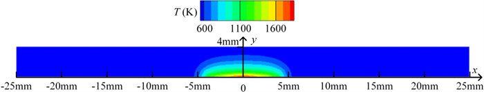
The simulation result of anode temperature in the case of 60 A current under 150 mT AMF is shown in figure 2. In the experiment [5], a pulse current with a duration of 4.6 ms was used. In order to reach a comparable condition, the model takes the temperature distribution of the anode at 4.6 ms. In the simulation, it is found that due to the short time scale involved in the study, the heat transfer effect of the contacts is small. The area with high temperature is mainly located in the center of the anode. The obvious temperature rise is mainly located in the area around the anode center with a radius of 2.5 mm, which is consistent with the experimental results.
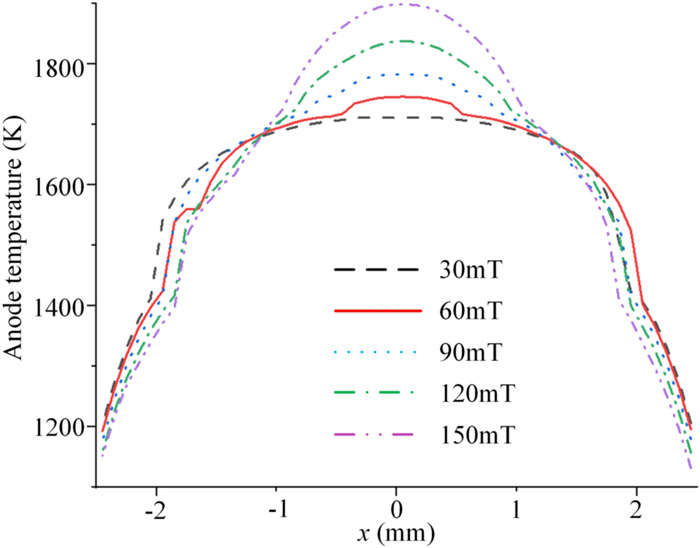
It can be seen from figure 3 that under the same AMF, the anode temperature decreases with the distance from the anode center along the radial direction. In addition, figure 3 also shows the radial distribution of anode surface temperature under different AMFs. The arc is diffused under the action of the pressure gradient. The temperature at the edge of anode is relatively low because the diffusion of the arc here is more obvious than that near the anode center, which results in lower energy flux density injected into the anode.
With the increase of AMF, the temperature of the anode center increases significantly. This is because the AMF has a corrective effect on the arc shape, and the diffusion of low current plasma jet is reduced under the action of the AMF. At the edge of the anode (about 2.5 mm away from the anode center) the anode temperature decreases with the increase of AMF. This is because the energy flux density injected into the edge of anode decreases, due to the concentration of energy flux density injected into anode.
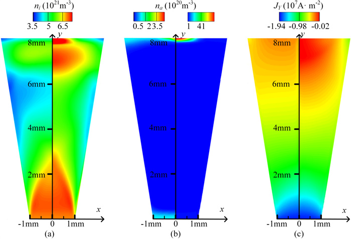
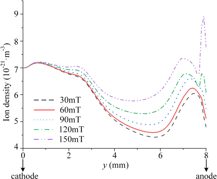
Figures 4–8 show the typical simulation results of various plasma parameters under different AMFs. The cathode is at y=0 mm, and the anode is at y=8 mm. As shown in figures 4(a) and 6, the maximum ion number density appears at the cathode and the minimum ion number density appears in the center of the gap. As the AMF increases, the ion number density near the axis increases correspondingly, which is caused by the corrective effect of the AMF. From y=0 mm to y=6 mm, the ion number density gradually decreases due to the pinch effect of the self-generated magnetic field. The current density there is so small that its influence can be ignored, so the plasma pressure gradient leads to the plasma diffusion as shown in equation (13). Between 6 and 7.5 mm from the cathode, the ion number density gradually increases. This is because the pressure caused by the vaporized atoms from the anode makes the ions decelerate here. Because of the conservation of mass, the ion number density increases accordingly. Near the anode side, ion density decreases since ions can be accelerated by the anode sheath. However, with an AMF higher than 120 mT, a significant rise in the ion density can be seen before its decrease due to the ionized atoms in front of the anode vapor area.
As shown in figure 4(b), the maximum atomic number density occurs in front of the anode. This is because the active anode emits a large number of atoms, namely anode vapor. With the increase of AMF, the atomic number density near the anode increases significantly because the corrective effect of stronger AMF makes the energy flux density injected into the anode higher. Then the anode is more active and can generate more anode vapor. As shown in figure 4(c), the current density gradually decreases from the cathode to the anode because the plasma is diffused from the cathode to the anode. On the anode surface, the current density is smaller at the center of the anode and larger at the edge because the plasma is forced to flow to the edge by the anode vapor. As the AMF increases, the current density at the center of the anode is lower due to more atomic vapor there.
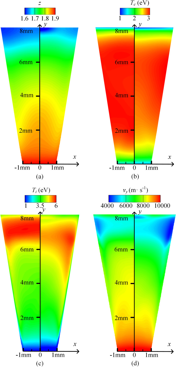
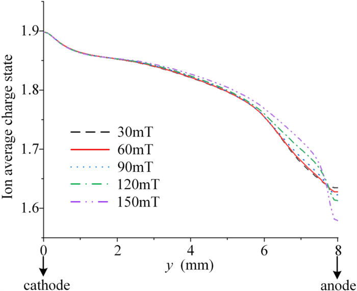
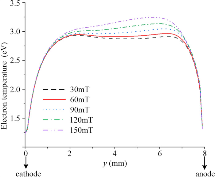
The average charge number distribution is shown in figures 5(a) and 7. As the AMF increases, the average number of charges in the area relatively far from the anode increases, which is closely related to the distribution of electron temperature. The average charge number in the area close to the anode decreases with the increase of AMF, because the increase of anode atomic vapor reduces the electron temperature there, due to the reduce of average charge number. The electron temperature distribution is shown in figures 5(b) and 8. As the current path shrinks, the current density near the central axis increases, and the electron temperature between the gaps increases with the increase in AMF. The decrease of the electron temperature near the anode is mainly due to acceleration by the anode sheath and ionization of atoms from the anode. The electron temperature in the region near the cathode is low than the start temperature of 3 eV because of the heat exchange between electrons and ions, which significantly reduces the electron temperature.
The ion temperature distribution is shown in figure 5(c). The ion velocity distributions are shown in the figure 5(d). It can be seen that the ion velocity distribution is negatively correlated with the ion temperature distribution. This is because the energy conservation of ions can play a very important role on the ion temperatur. Under jet conditions, the ion velocity is high and the kinetic energy is high. Therefore, when the deceleration of ions is large, the temperature rise will be significant. Near the anode, the anode vapor will decelerate the ions. Therefore, the ion temperature will increase significantly near the anode, and can even be higher than the electron temperature. With the AMF of 150 mT, near the anode, the ion temperature is higher near the boundary. This is mainly because the large amount of anode vapor generated from the core of the anode under the condition of large AMF has a cooling effect on the ions from the cathode.
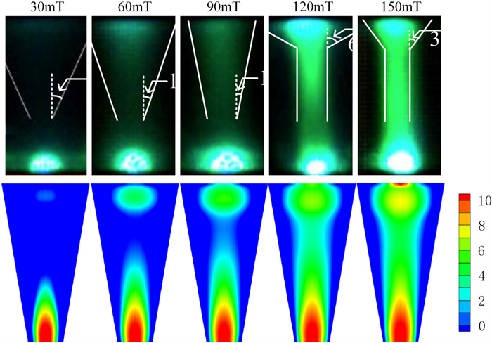
The comparison between the plasma luminous intensity distributions affected by the ion number density and atomic number density and the experimental results is shown in figure 9. In the experiment, the exposure time of the high-speed camera is set to 2 μs, and the interval between two adjacent frames is about 20 μs. The calculation method of the simulation result is: the two-dimensional simulation result is rotationally symmetric to obtain the three-dimensional simulation result. The cross section is considered as an xoy plane. The luminous intensity at any position in the simulation is obtained by the line integration of the sum of the ion number density and the atomic number density in the x direction passing the point. Here, the normalized calculation (0–10) of the plasma luminescence intensity obtained after integration is carried out. It can be seen from [26–28] that both atoms and ions contribute to the luminous intensity. So in this paper, the contribution ratio of the two is set to 1:1, refer to [24]. As shown in the figure, the maximum brightness of the plasma appears in two regions: one (global maximum) is close to the cathode, and the other one is close to the anode. The first maximum is caused by the high-density plasma near the cathode spot. While the second one is due to the deceleration of the plasma from cathode affected by the pressure of anode atomic vapor and the anode atomic vapor itself. Therefore, the brightness here increases with the increase of the AMF and the atomic density near the anode. In addition, the plasma brightness in the gap also increases with the increase of AMF. The experimental results in the upper part of figure 9 show that with the increase of AMF, the brightness of the cathode spot increases slightly, and the brightness of the area near the anode gradually increases. The calculated appearance is very consistent with the appearance of the plasma jet in the literature [5]. The lines and angles shown in the figure are from the original reference.
In this work, a simulation model considering anode evaporation under strong AMF is built to study LCVA. Based on the simulation results, the vacuum arc jet property observed in the experiments is analysed. Here are some conclusions.
With the increase of AMF strength, the anode temperature at the central area increases, leading to higher vaporized atom density. This is because AMF can weaken the diffusion of LCVA, and then increase the energy flux density injected into the anode center. The generation of atomic vapor from the anode is sufficient to explain the appearance of LCVA near the anode under strong AMF. With the strengthening of the external AMF, the bright spot appears on the anode surface. The brightness of 'anode spots'increases with the increase of external AMF. During this process, the arc shape gradually changes from a cone to a dumbbell shape. This is in good agreement with the experimental results.
This research was supported by National Natural Science Foundation of China (Nos. U1866202 and 51877164) and State Key Laboratory of Electrical Insulation and Power Equipment Fund (No. EIPE19128).
| [1] |
Wang L J et al 2005 J. Phys. D: Appl. Phys.
38 1034 doi: 10.1088/0022-3727/38/7/011
|
| [2] |
Schulman M B and Schellekens H 2000 IEEE Trans. Plasma Sci.
28 443 doi: 10.1109/27.848103
|
| [3] |
Chaly A M et al 2009 IEEE Trans. Plasma Sci.
37 1426 doi: 10.1109/TPS.2009.2024670
|
| [4] |
Zabello K K et al 2011 IEEE Trans. Plasma Sci.
39 1319 doi: 10.1109/TPS.2011.2120626
|
| [5] |
Wang C et al 2016 J. Phys. D: Appl. Phys.
49 135203 doi: 10.1088/0022-3727/49/13/135203
|
| [6] |
Shkol'nik S M 2003 IEEE Trans. Plasma Sci.
31 832 doi: 10.1109/TPS.2003.818442
|
| [7] |
Popov S A et al 2012 Techn. Phys.
57 938 doi: 10.1134/S1063784212070183
|
| [8] |
Boxman R L and Goldsmith S 1983 J. Appl. Phys.
54 592 doi: 10.1063/1.332063
|
| [9] |
Wang L et al 2008 Eur. Phys. J. Appl. Phys.
41 243 doi: 10.1051/epjap:2008020
|
| [10] |
Wang L J et al 2020 Phys Plasmas
27 023514 doi: 10.1063/1.5129780
|
| [11] |
Wang L J et al 2015 J. Appl. Phys.
117 243301 doi: 10.1063/1.4922495
|
| [12] |
Schade E and Shmelev D L 2003 IEEE Trans. Plasma Sci.
31 890 doi: 10.1109/TPS.2003.818436
|
| [13] |
Shmelev D L and Uimanov I V 2015 IEEE Trans. Plasma Sci.
43 2261 doi: 10.1109/TPS.2015.2430372
|
| [14] |
Wang L J et al 2017 J. Phys. D: Appl. Phys.
50 095203 doi: 10.1088/1361-6463/aa5620
|
| [15] |
Huang X L et al 2015 IEEE Trans. Plasma Sci.
43 2283 doi: 10.1109/TPS.2015.2443811
|
| [16] |
Beilis I I et al 1998 J. Appl. Phys.
83 709 doi: 10.1063/1.366742
|
| [17] |
Wang L J et al 2016 AIP Adv.
6 125019 doi: 10.1063/1.4972060
|
| [18] |
Shmelev D L,Uimanov I V and Frolova V P 2018 Numerical simulation of low-current vacuum arc plasma jet in strong axial magnetic field 2018 28th Int. Symp. on Discharges and Electrical Insulation in Vacuum (ISDEIV)(Greifswald, Germany)(IEEE) p 377
|
| [19] |
Wang L J et al 2006 J. Appl. Phys.
100 113304 doi: 10.1063/1.2388734
|
| [20] |
Wang L J et al 2019 Appl. Phys. Lett.
115 014101 doi: 10.1063/1.5110538
|
| [21] |
Wang L et al 2019 IEEE Trans. Plasma Sci.
47 3496 doi: 10.1109/tps.2019.2899659
|
| [22] |
Yang Z et al 2019 J. Appl. Phys.
126 193306 doi: 10.1063/1.5127964
|
| [23] |
Weast R C 1974 Handbook of Chemistry and Physics(Boca Raton, FLCRC Press)
|
| [24] |
Popov S A et al 2012 Tech. Phys.
57 938 doi: 10.1134/s1063784212070183
|
| [25] |
Khakpour A, Franke S and Methling R 2017 IEEE Trans. Plasma Sci.
99 1
|
| [26] |
Yang Z, Wang L and Gortschakow S 2021 J. Phys. D: Appl. Phys.
54 505201 doi: 10.1088/1361-6463/ac25b0
|
| [1] | Xianhai PANG (庞先海), Zixi LIU (刘紫熹), Shixin XIU (修士新), Dingyu FENG (冯顶瑜). Arc characteristics during the instability stage on transverse magnetic field contacts[J]. Plasma Science and Technology, 2018, 20(9): 95505-095505. DOI: 10.1088/2058-6272/aac50a |
| [2] | Xianhai PANG (庞先海), Ting WANG (王婷), Shixin XIU (修士新), Junfei YANG (杨俊飞), Hao JING (景皓). Investigation of cathode spot characteristics in vacuum under transverse magnetic field (TMF) contacts[J]. Plasma Science and Technology, 2018, 20(8): 85502-085502. DOI: 10.1088/2058-6272/aab782 |
| [3] | Yi CHEN (陈毅), Fei YANG (杨飞), Hao SUN (孙昊), Yi WU (吴翊), Chunping NIU (纽春萍), Mingzhe RONG (荣命哲). Influence of the axial magnetic field on sheath development after current zero in a vacuum circuit breaker[J]. Plasma Science and Technology, 2017, 19(6): 64003-064003. DOI: 10.1088/2058-6272/aa65c8 |
| [4] | WANG Cheng (王城), CHEN Tang (陈瑭), LI Wanwan (李皖皖), ZHA Jun (査俊), XIA Weidong (夏维东). Axial Magnetic Field Effects on Xenon Short-Arc Lamps[J]. Plasma Science and Technology, 2014, 16(12): 1096-1099. DOI: 10.1088/1009-0630/16/12/03 |
| [5] | ZHU Liying(朱立颖), WU Jianwen(武建文), JIANG Yuan(蒋原). Motion and Splitting of Vacuum Arc Column in Transverse Magnetic Field Contacts at Intermediate-Frequency[J]. Plasma Science and Technology, 2014, 16(5): 454-459. DOI: 10.1088/1009-0630/16/5/03 |
| [6] | LIU Wenzheng(刘文正), WANG Hao(王浩), DOU Zhijun(窦志军). Impact of the Insulator on the Electric Field and Generation Characteristics of Vacuum Arc Metal Plasmas[J]. Plasma Science and Technology, 2014, 16(2): 134-141. DOI: 10.1088/1009-0630/16/2/09 |
| [7] | WANG Lijun (王立军), YANG Dingge (杨鼎革), JIA Shenli (贾申利), WANG Liuhuo (王流火), SHI Zongqian (史宗谦). Vacuum Arc Characteristics Simulation at Different Moments Under Power-Frequency Current[J]. Plasma Science and Technology, 2012, 14(3): 227-234. DOI: 10.1088/1009-0630/14/3/08 |
| [8] | G.Yu. YUSHKOV, K.P. SAVKIN, A.G. NIKOLAEV, E.M. OKS, A.V. VODOPYANOV, I.V. IZOTOV, D.A. MANSFELD. Formation of Multicharged Metal Ions in Vacuum Arc Plasma Heated by Gyrotron Radiation[J]. Plasma Science and Technology, 2011, 13(5): 596-599. |
| [9] | ZHANG Ling, JIA Shenli, WANG Lijun, SHI Zongqian. Simulation of vacuum arc characteristics under four kinds of axial magnetic fields and comparison with experimental results[J]. Plasma Science and Technology, 2011, 13(4): 462-469. |
| [10] | JIA Shenli, SONG Xiaochuan, HUO Xintao, SHI Zongqian, WANG Lijun. Investigation of Vacuum Arc Voltage Characteristics Under Different Axial Magnetic Field Profiles[J]. Plasma Science and Technology, 2010, 12(6): 729-733. |
| 1. | Liu, Z., Song, M., Wang, Z. et al. Effects of anode evaporation process on the anode sheath characteristics in vacuum arc plasma. Journal of Physics D: Applied Physics, 2025, 58(11): 115201. DOI:10.1088/1361-6463/ad7c5c |
| 2. | Li, Y., Zhang, R., Yang, K. et al. Numerical investigations of AC arcs’ thermal characteristics in the short gap of copper-cored wires. Scientific Reports, 2024, 14(1): 4227. DOI:10.1038/s41598-024-54911-2 |
| 3. | Ye, J., Yang, P., Yuan, Z. et al. 3D simulation of the interaction between double copper cathode spot jets in vacuum arc. AIP Advances, 2024, 14(9): 095318. DOI:10.1063/5.0229021 |
| 4. | Jiang, Y., Ma, S., Li, Q. et al. Non-uniform pinching of short-gap intermediate frequency vacuum arc without controlled magnetic field. Vacuum, 2024. DOI:10.1016/j.vacuum.2024.113394 |
| 5. | Li, J., Peng, S., Yi, C. et al. Optimization Research on DC Air Circuit Breaker at High Altitudes Based on Arc Root Stagnation and Arc Reverse Movement Phenomena. Journal of Electrical Engineering and Technology, 2024, 19(5): 3551-3568. DOI:10.1007/s42835-023-01633-6 |
| 6. | Li, Y., Zhang, R., Yang, K. et al. Research on an Equivalent Heat Source Model of the AC Arc in the Short Gap of a Copper-Core Cable and a Fire Risk Assessment Method. Sensors, 2024, 24(5): 1443. DOI:10.3390/s24051443 |
| 7. | Wang, L., Chen, J., Zhang, Z. et al. Research Progress of Modeling and Simulation of Vacuum Arcs Considering Multicomponents With Different Anode Modes. IEEE Transactions on Plasma Science, 2024, 52(9): 4402-4418. DOI:10.1109/TPS.2024.3485966 |
| 8. | Wang, L., Chen, J., Zhang, Z. et al. Numerical simulation of multi-components vacuum arcs with different anode modes: A Review. Proceedings - International Symposium on Discharges and Electrical Insulation in Vacuum, ISDEIV, 2023. DOI:10.23919/ISDEIV55268.2023.10200029 |
Figures(9) / Tables(1)
Supported by: Beijing Renhe Information Technology Co., Ltd. 
| Symbol | Meaning |
| ns | Total number density of species s |
| e | Unit charge |
| Ionization rate | |
| Current density | |
| Ts | Average temperature of species s |
| zi | Average ion charge number |
| Average velocity of species s | |
| κ | Specific heat ratio |
| ∆H | Latent heat |
| r | Sensible enthalpy |
| σ | Electric conductivity |
| WCuj | Ionization energy |
| νei | Collision frequency between electrons and ions |
| μ0 | Vacuum permeability |
| αCuj | Ionization rate coefficient |
| βCuj | Recombination rate coefficient |
| C | Constant (C=2.6×10⁻²¹ m2·eV-1) |
| WH | Ionization energy of hydrogen |
| λs | Average thermal conductivity of species |
| M | Mach number |
| Hm | Enthalpy value |
DownLoad:
CSV