Recent experimental data for anomalous magnetic moments strongly indicates the existence of new physics beyond the Standard Model. Energetic μ+ bunches are relevant to μ+ rare decay, spin rotation, resonance and relaxation (μSR) technology, future muon colliders, and neutrino factories. In this paper, we propose prompt μ+ acceleration in a nonlinear toroidal wakefield driven by a shaped steep-rising-front Laguerre–Gaussian (LG) laser pulse. An analytical model is described, which shows that a μ+ beam can be focused by an electron cylinder at the centerline of a toroidal bubble and accelerated by the front part of the longitudinal wakefield. A shaped LG laser with a short rise time can push plasma electrons, generating a higher-density electron sheath at the front of the bubble, which can enhance the acceleration field. The acceleration field driven by the shaped steep-rising-front LG laser pulse is about four times greater than that driven by a normal LG laser pulse. Our simulation results show that a 300 MeV μ+ bunch can be accelerated to 2 GeV and its transverse size is focused from an initial value of w0 = 5 μm to w = 2 μm in the toroidal bubble driven by the shaped steep-rising-front LG laser pulse with a normalized amplitude of a = 22.
Recently, there has been increasing interest in the exploration of new physics beyond the Standard Model using the μ+ rare decay [1–3] and the anomalous magnetic moment [4–6]. The unstable particle, μ+(μ−) with a rest mass mμ = 207me and a rest lifetime τ = 2.2 μs has been applied in many fields (me is the rest mass of the electron). Energetic μ+(μ−) bunches can be used to make future neutrino factories [7, 8] and muon colliders [9, 10] become a reality. In the field of spin rotation, resonance, and relaxation (μSR) technology [11–14], an energetic μ+ beam can pass through the wall of a container to probe materials in complex environments. The two available types of μ+(μ−) are low-flux GeV cosmic muons [15, 16] and low-energy muon sources produced by traditional accelerators [17–19]. The cosmic muons are too low-flux and the muon sources produced by traditional accelerators are too short-lived to explore new physics.
Plasma-based accelerators [20–23] can offer extremely high acceleration fields of several hundred GV/m and can be applied to the study of high-energy physics and particle sources. Recently, a μ− beam was accelerated to GeV or 10 GeV in a plasma wakefield [24, 25]. However, the acceleration of a μ+ beam in a laser plasma wakefield has not been explored. A μ+ beam would be defocused by the transverse field in a regular bubble driven by a Gaussian laser pulse.
Using three-dimensional (3D) particle-in-cell (PIC) simulations performed by Epoch3D [26], we propose a prompt μ+ acceleration scheme in a nonlinear toroidal wakefield [27–29] driven by a shaped Laguerre–Gaussian (LG) laser pulse [30]. A collimated muon bunch with a peak energy of several hundred MeV was recently produced by a GeV electron beam interacting with a high-Z target [31, 32]. In our simulations, we focus on μ+ acceleration and assume that the required μ+ beam has been injected into the wakefield. An analytical model is given, which shows that a μ+ beam can be focused by an electron cylinder at the centerline of the toroidal bubble and accelerated in the front part of the longitudinal wakefield Ex. The simulation results show that in the wakefield driven by a LG laser pulse, the transverse size of the μ+ beam is focused from an initial value of w0 = 5 μm to w = 2 μm within several picoseconds. In addition, the peak energy of the accelerated μ+ bunch, which had an initial energy of 300 MeV, is about 500 MeV. A LG laser pulse shaped by a near-critical-density plasma has a shorter rise time. The shaped steep-rising-front LG laser pushes plasma electrons forward, causing an electron sheath with larger σe≡nshΔxnsh to be formed at the front of the toroidal bubble, where nsh and Δxnsh are the density and width of the electron sheath, respectively. The acceleration field Ex is proportional to σe. The simulation results show that in the toroidal wakefield driven by a shaped steep-rising-front LG laser, the peak energy of the accelerated μ+ bunch with an initial energy of 300 MeV is about 2 GeV, and the transverse size of the μ+ bunch is also focused from an initial value of w0 = 5 μm to w = 2 μm within several picoseconds.
In cylindrical coordinates, the transverse distribution of the normalized amplitude of an LG laser can be expressed as:
where a0 is the maximum normalized amplitude, cl,p is the normalizing factor, w is the laser spot size, and Llp(ξ) is the generalized Laguerre polynomial. In our simulations, the Gaussian model of the laser pulse used is the LG1,0 model, which can be expressed as:
a1, 0(r,θ)=a0c1, 0w√2rwexp(−r2w2)exp(−iθ),
(2)
where c1, 0 ≈ 1.67w. Equation (2) shows that the laser intensity at r = 0 is zero. Due to the ponderomotive force of the LG laser pulse, plasma electrons are squeezed into the center axis and form an electron cylinder. This center electron cylinder has a higher density than that of the background electrons. The ponderomotive force of the LG laser pulse can also exclude nearby plasma electrons. Plasma protons can be considered as unmovable. The homogeneous protons pull the excluded electrons back to the center axis. Therefore, a toroidal bubble is formed.
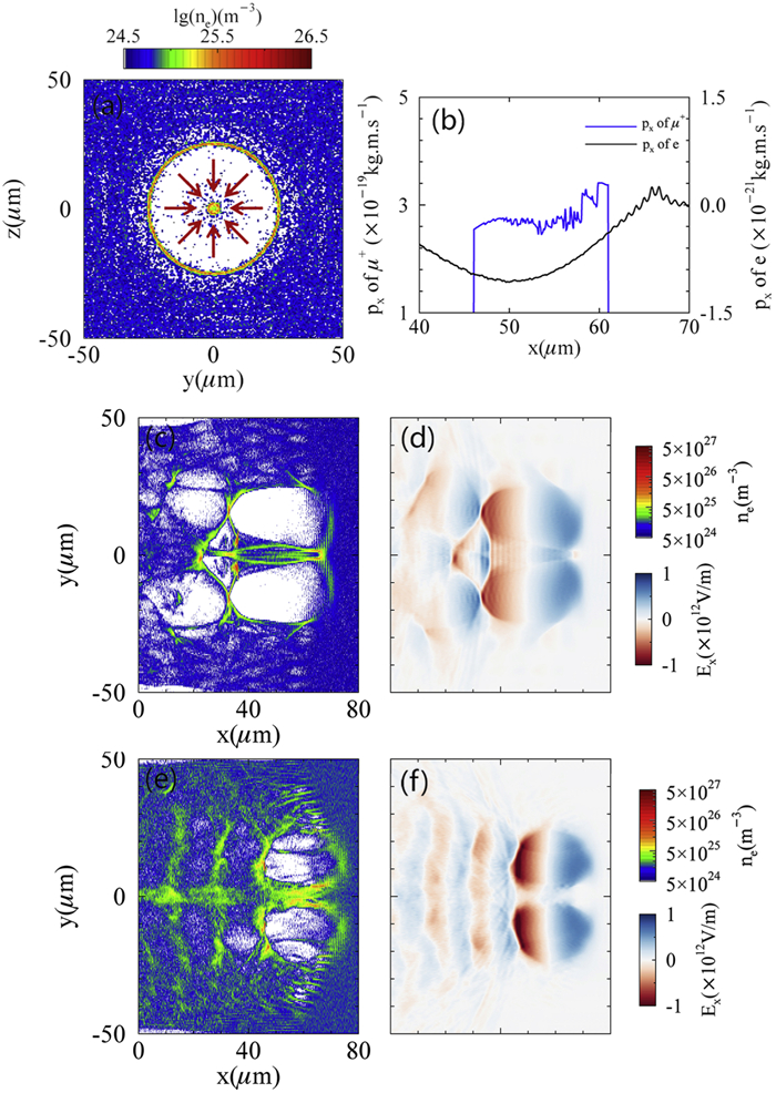
A μ+ beam can be accelerated and focused in a nonlinear toroidal wakefield [33, 34] driven by an LG laser pulse. Figure 1(a) shows a transverse density slice of a toroidal bubble. The red arrow in figure 1(a) shows the direction of the transverse electric field produced by the central electron cylinder. The transverse electric field of the central electron cylinder forms a focusing field for the μ+ beam. In figure 1(b), negative momentum means that the central electrons are moving in the negative x direction. Therefore, their magnetic field is a focusing field. The toroidal wakefields shown in figures 1(c), (e) were driven by the same LG laser pulse at different plasma densities of ne = 5 × 1024 m−3 and ne = 1 × 1025 m−3, and look like two spherical bubbles. Figure 1(c) shows that in a nonlinear scheme, the two spherical wakefields have overlapping ranges. Figure 1(d) shows that the longitudinal wakefield Ex hardly varies with r, i.e. ∂Ex/∂r ≃ 0. Figure 1(e) shows that at the onset of the nonlinear scheme, the two spherical wakefields have no overlap. The longitudinal wakefield Ex is close to zero at r = 0, as shown in figure 1(f). Only the nonlinear toroidal wakefield can accelerate and focus the μ+beam.
Figure
1.
Simulation results illustrating focusing (a), (b) and acceleration (c), (d) fields for a μ+ beam in a nonlinear toroidal wakefield. (a) shows a transverse slice of the toroidal wakefield as shown in (c) at x = 60 μm. (b) shows plots of the momentum in the x direction of the electrons and μ+ at the centerline of the toroidal wakefield. (c) shows a longitudinal slice of the electron density at z = 0 μm in a plasma with a density of ne = 5 × 1024 m−3. (d) shows the longitudinal wakefield Ex corresponding to (c). (e) shows a longitudinal slice of the toroidal wakefield at z = 0 μm in a plasma with a higher density of ne = 1 × 1025 m−3. (f) shows the Ex corresponding to (e).
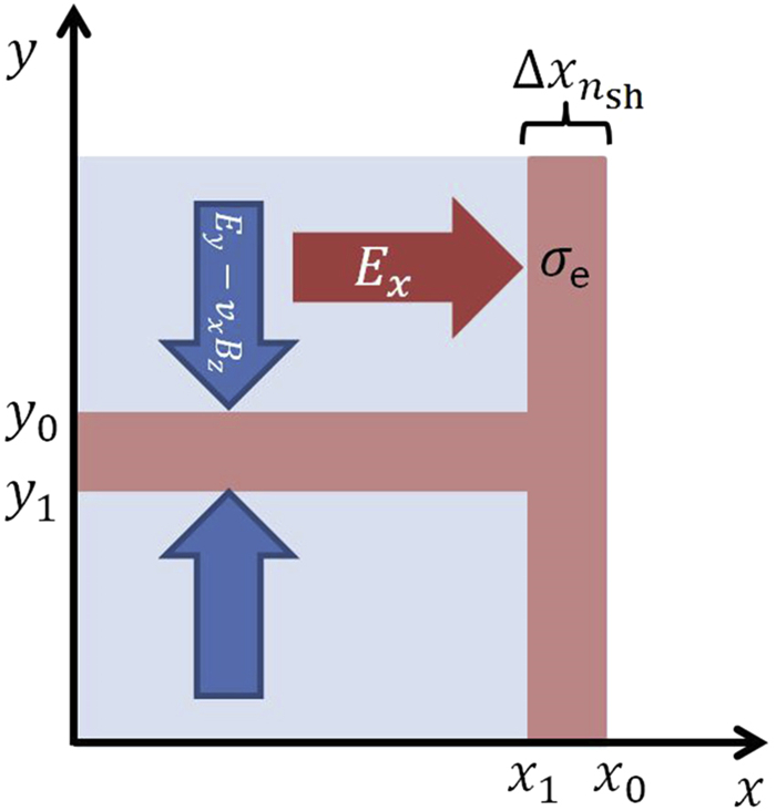
We propose a simple physical model shown in figure 2 to illustrate the focusing and accelerating of the μ+ beam in the nonlinear toroidal wakefield driven by a LG laser. The blue arrows is the direction of the focusing force. The red arrow is the direction of the longitudinal wakefield. nsh is the density of the electron sheath at the front of the wakefield. Δxnsh is the width of this electron sheath. The σe is defined as σe≡nshΔxnsh. The longitudinal wakefield Ex is equal to zero at x = 0, x0. For 0 < x < x1, the longitudinal wakefield Ex is the acceleration field for positive particles. In the range of 0 < x < x1, y < y1 and y > y0, the plasma electron density is close to zero. The electron cylinder at the centerline of the toroidal provides the focusing force for positive particles and the electron sheath at the front of the toroidal provides the acceleration field. In the wakefield coordinate, the acceleration field can be considered as a static electric field. The acceleration field in the wakefield coordinate is equal to that in the laboratory coordinate. The Gauss's law for the static electric field can be expressed as:
∮s→Ed→S=qε0,
(3)
Figure
2.
A physical model of the focusing and accelerating of a μ+ beam in a toroidal wakefield driven by a LG laser pulse. The physical model is in the range of the red dotted line as shown in (c). The center red rectangle represents the center electron cylinder. The right red rectangle represents the electron sheath at the front of the toroidal wakefield.
where ∮s is the integral of the closed surface S, →E is the electric field, q is the charge inner the closed surface S, ε0 is the vacuum permittivity. The six surfaces of the blue cuboid form the closed surface S=s1+s1′+s2+s2′+s3+s3′. We assume that s1 and s1′ are infinitesimal, which causes the electric field on s2 and s3 almost equal to that on s2′ and s3′, respectively. The electric field on s1′ is equal to zero. Therefore in the range of 0 < x < x0, y < y1 and y > y0, the acceleration field on s1 can be expressed as:
Ex=[−∫xx0nedx−np(x0−x)]eε0,
(4)
where ne is the electron density, np is the proton density and considered as a constant, e is the elementary charge. It is assumed that the density of the electron sheath at the front of the toroidal is a constant nsh. The σe is defined as σe≡nshΔxnsh. In the range of 0 < x < x0, y < y1 and y > y0, the acceleration field Ex can be simplified as:
Ex=[σe−np(x0−x)]eε0.
(5)
equation (5) shows that for a given position on the x-axis, the acceleration field Ex is proportional to σe.
3.
Three-dimensional simulations of the μ+ acceleration in a toroidal wakefield driven by a LG laser pulse
We implement PIC simulations to explore the focusing and accelerating of a μ+ beam in a toroidal wakefield driven by a LG laser pulse. Those simulation results as shown in figure 3 are obtained using a LG laser with the spot size, w = 15 μm, normalized amplitude, a0 = 22, and pulse width, τ = 25 fs. At the beginning of the simulation, a 300 MeV μ+ beam is placed at the front part of the acceleration field where the LG laser pulse also exists as shown in figures 3(a) and (g). Compared with positrons, μ+ has a slower response to the oscillating field of the LG laser pulse. Therefore, the μ+ beam and the LG laser pulse can be placed at the same position in the toroidal wakfield, which ensures that the μ+ beam can be accelerated with a longer acceleration length. Detailed simulation parameters are shown in configuration A of table 1. The Gauss (x, x0, w) function as shown in table 1 calculate a Gaussian profile in variable x centred on x0 with a characteristic width w and be expressed as: f(x)=exp[−(x−x0w)2].
Figure
3.
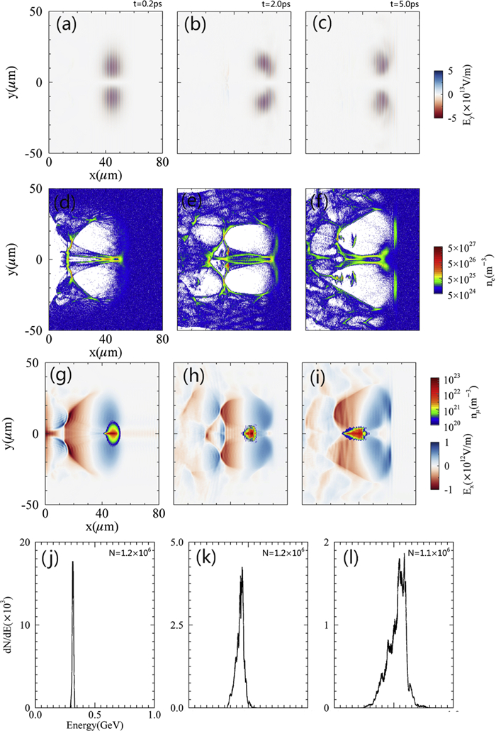
The μ+ acceleration in a toroidal wakefield driven by a LG laser pulse. (a)–(i) show the longitudinal slices of the simulation box at the plane of z = 0 μm. (a)–(c) show the evolution of the laser pulse. (d)–(f) show the longitudinal structure of the toroidal wakefield. (g)–(i) show the longitudinal wakefield Ex and the density of the μ+ bunch. (j)–(l) are the energy spectrum of the μ+ bunch.
Table
1.
Detailed simulation parameters for three configurations: (A), (B), and (C). We only list the parameters of configurations B and C that differ from those of configuration A.
The snapshots shown in figure 3 are taken at the beginning, middle, and end of the acceleration, corresponding to simulation times of t = 0.2 ps, t = 2.0 ps, and t = 5.0 ps. Figures 3(a)–(c) show that an LG laser pulse can be self-guided, which is attributed to the distribution of the refractive index at the front of the toroidal wakefield. Figures 3(d)–(f) show that the toroidal wakefield propagates stably within 5 ps, and provides continuous acceleration and focusing fields for the μ+ beam. The acceleration field is separated at five picoseconds, since the central electron cylinder retroacts on the LG laser pulse. Figures 3(g)–(i) show that the transverse size of the μ+ bunch is focused from a value of w0 = 5 μm to w = 2 μm within several picoseconds by the central electron cylinder. During the acceleration process the μ+ bunch always moves back toward the rear edge of the toroidal wakefield and finally enters the decelerating field at five picoseconds. The final peak energy of the μ+ beam is about 500 MeV. The energy spread is , where ΔE is the full width at half maximum (FWHM) and E is the peak energy.
4.
The stronger acceleration field driven by a shaped steep-rising-front LG laser for positive particle
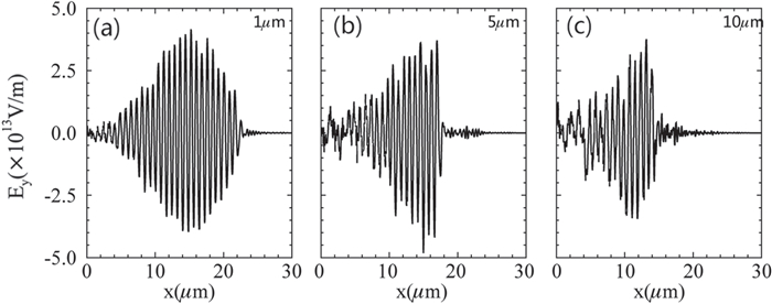
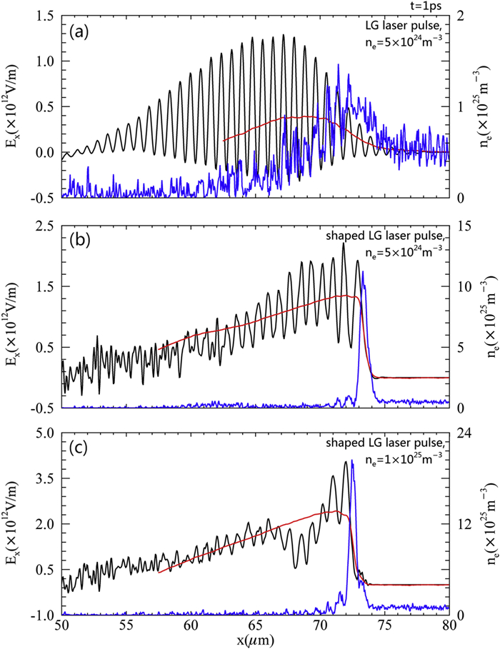
The shaping of a Gaussian laser pulse was proposed by H W Wang and coworkers [35]. They demonstrate that as relativistic self-focusing (RSF) [36, 37], relativistic self-phase modulation (RSPM) [38, 39], and relativistic transparency occur in the interaction between a laser pulse and a near-critical plasma, three shaping effects take place: laser intensity enhancement, laser profile steepening, and absorption of the nonrelativistic prepulse. Our simulation results show that an LG laser pulse can also be shaped by a near-critical plasma. The shaping effect is controlled by the length of the near-critical plasma. Figure 4 shows the transverse oscillating electric fields of LG laser pulses shaped by near-critical-density plasmas with lengths of 1 μm, 5 μm and 10 μm, respectively. The rise time of the shaped LG laser pulse shown in figure 4(a) is longer compared with that of the shaped LG laser pulse shown in figure 4(b), which limits the maximum transversal wakefield driven by this shaped LG laser pulse. Figure 4(c) shows that if the length of the near-critical plasma is 10 μm, the maximum amount of LG laser pulse energy is consumed by the near-critical plasma. Therefore, in our simulations, the length of the near-critical plasma is set to 5 μm. Figure 5 shows the influences of the shaping of the LG laser pulse and the plasma density on the acceleration field. The simulation results in figures 5(a), (b), and (c) are obtained using the parameters shown in configurations A, B, and C, respectively. Compared with the blue line in figure 5(a), the blue line in figure 5(b) shows that the electron sheath generated by the shaped laser pulse has a larger σe. Furthermore, the blue line in figure 5(c) shows that in a higher-density plasma, σe is larger. Corresponding to those black lines, the red lines in figure 5 show the theoretical results of equation (5). The electron density ne of equation (5) is represented by the blue lines. The theoretical results agree with the simulation results. The red line in figure 5(c) shows that in a higher-density plasma, the acceleration field driven by a shaped steep-rising-front LG laser is the largest and can reach about 2.4 TV/m.
Figure
4.
Comparison of LG laser pulses shaped by near-critical-density plasmas with different lengths: 1 μm, 5 μm, and 10 μm. Figures 4(a)–(c) are all one-dimensional simulation results located at y = 0 μm, z = 10 μm in the three-dimensional simulation box.
Figure
5.
Comparison of the wakefields driven by an LG laser pulse (a) and a shaped LG laser pulse (b)–(c), illustrating that the shaped steep-rising-front LG laser can stimulate a higher acceleration gradient. The blue lines represent the simulated results for the electron density. The black and red lines represent the simulated and theoretical results for the acceleration field Ex. The blue and black lines are located at y = 0 μm, z = 10 μm in the three-dimensional simulation box.
5.
Three-dimensional simulations of μ+ acceleration in a toroidal wakefield driven by a shaped steep-rising-front LG laser pulse
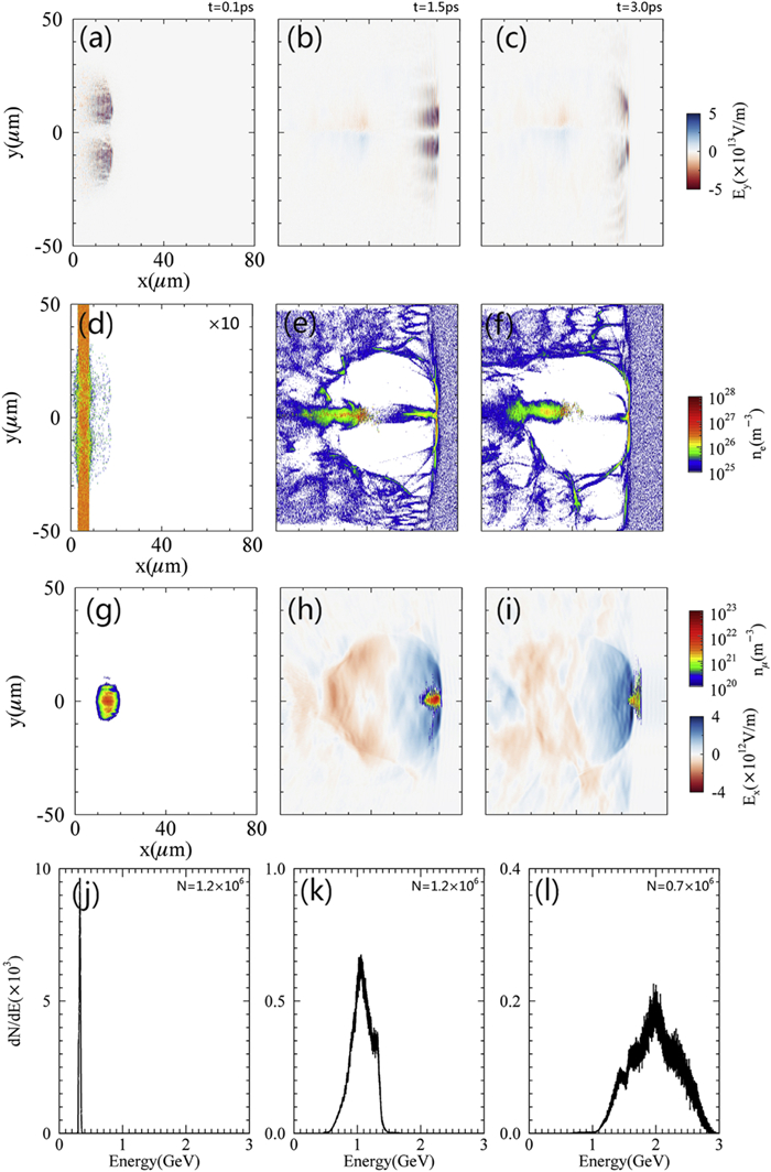
Figure 6 shows the evolution of the μ+ acceleration process in a toroidal wakefield driven by a shaped steep-rising-front LG laser. The laser parameters are the same as those of figure 3. A μ+ bunch with an initial energy of 300 MeV can be located at the front part of the wakefield by adjusting its injection time. The detailed simulation parameters are listed in configuration C of table 1. Figure 6 shows that in a plasma with a density of ne = 1 × 1025 m−3, a shaped steep-rising-front LG laser pulse can drive the acceleration field at the centerline of the toroidal bubble for positive particles. Although the central electron cylinder is unstable during acceleration, the transverse size of the μ+ beam is also focused. The snapshots shown in figure 6 are taken at the beginning, middle, and end of the acceleration corresponding to simulation times of t = 0.1 ps, t = 1.5 ps, and t = 3.0 ps. Figure 6(a) shows that an LG laser pulse is shaped by a near-critical-density plasma. The shaped LG laser has a shorter rise time of tr = 13 fs and a higher amplitude of Ey = 5 × 10¹³ V/m, compared to the LG laser shown in figure 3(a) with a rise time of tr = 33 fs and an amplitude of Ey = 4 × 10¹³ V/m. Figures 6(b) and (c) show that the LG laser pulse is self-guided. A large proportion of the laser energy is depleted at t = 3 ps. Figures 6(e), (f), (h), and (i) show that the acceleration field is stable within 3 ps and at up to 4 × 10¹² V/m. Figures 6(g)–(i) show that the transverse size of the μ+ bunch is focused from the initial value of w0 = 5 μm to w = 2 μm within several picoseconds by the central electron cylinder. At the beginning of the acceleration, the μ+ bunch with an initial energy of 300 MeV moves backward relative to the toroidal bubble and is simultaneously accelerated. When the velocity of the μ+ bunch is larger than that of the toroidal wakefield, it moves forward relative to the toroidal bubble and finally overtakes the acceleration field. In the toroidal wakefield driven by a shaped steep-rising-front LG laser pulse, the final peak energy of an accelerated μ+ bunch with an initial energy of 300 MeV is about 2 GeV. The energy spread is .
Figure
6.
The acceleration process of a μ+ beam in a toroidal wakefield driven by a shaped steep-rising-front LG laser pulse. (a)–(i) show longitudinal slices of the simulation box at the plane z = 0 μm. The scaling factor for (d) is ×10. The scaling factor for the other figures is × 1. (a) shows the shaping of an LG laser pulse in a near-critical-density plasma. (b), (c) show the evolution of the laser pulse. (d) shows the density distribution of a near-critical-density plasma. (e), (f) show the longitudinal structure of a toroidal bubble. (g) shows the initial density distribution of the μ+ beam. (h), (i) show the longitudinal field Ex and the density distribution of the μ+ beam. (j)–(l) show the energy spectrum of the μ+ beam.
6.
Comparison of the peak energies of the accelerated muon beam for three different simulation configurations
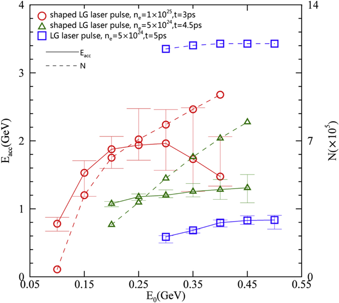
Figure 7 mainly shows the influences of the shaping of the LG laser pulse and the plasma density on the peak energy of the accelerated μ+ bunch. The circles, triangles, and squares represent simulation times of 3 ps, 4.5 ps, and 5 ps, using the simulation parameters shown in configurations (A), (B), and (C) of table 1, respectively. For the red circles shown in figure 7, the maximum LG laser pulse energy was consumed at a simulation time of t = 3 ps. When the initial energy is 100 MeV, most muons cannot catch up with the focusing and acceleration fields. With an initial energy increase from 100 MeV to 300 MeV, the peak energy and number of muons in the accelerated μ+ bunch both increase. When the initial energy increases from 300 MeV to 450 MeV, the number of muons still increases, but the peak energy decreases; the reason for this is that with a higher initial energy, the μ+ bunch overtakes the wakefield earlier and has a shorter acceleration time. For the green triangles, the wakefield collapsed at the simulated time of t = 4.5 ps. When the initial energy is increased, the peak energy and the number of muons in the accelerated μ+ bunch also both increase. For the blue squares, the wakefield collapsed at a simulated time of t = 5 ps. When the initial energy is increased, the peak energy of the accelerated μ+ bunch increases and the number of muons almost remains constant due to the stable focusing field driven by a normal LG laser pulse. Compared with the blue solid line shown in figure 7, the red solid line shows that in the toroidal wakefield driven by a shaped steep-rising-front LG laser pulse, the peak energy of the μ+ beam can be increased by three to four times compared to that of a μ+ beam accelerated in a toroidal wakefield driven by a normal LG laser pulse.
Figure
7.
The initial energy E0 of the μ+ bunch versus the peak energy Eacc and the total number of muons after the μ+ bunch is accelerated. The solid lines represent the peak energy Eacc of the accelerated μ+ bunch. The y error bars only represent the FWHM of the energy spectrums. The dashed lines represent the total number of the muons at the corresponding moment.
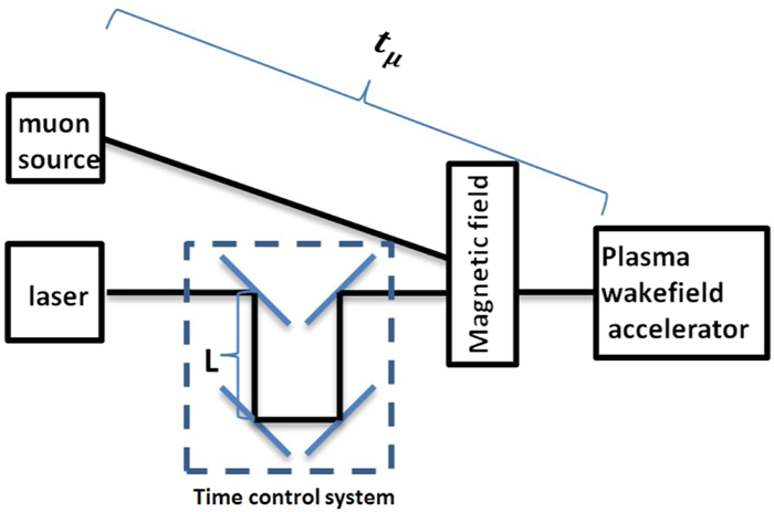
We also considered the synchronization of the laser and muon beam. In PIC simulations, synchronization can be realized by controlling the injection times of the laser and the muon beam. However, in experiments, the synchronization will be very complicated. Here, we propose the preliminary time control system as shown in figure 8 to realize synchronization. We assume that the time of muon beam injection into the plasma accelerator from the muon source, tμ, is fixed. The time of the laser pulse injection into the plasma accelerator is modulated by the distance between the upper and lower mirrors, L, as shown in figure 8. When L is changed by 0.15 μm, the timing of the laser pulse injected into the plasma accelerator is altered by 1 fs. The main difficulty in realizing the synchronization is finding a way to precisely confirm tμ, which will be included in our next work plan.
Figure
8.
A preliminary time control system to realize the synchronization of the laser and muon beam. Here, tμ is the time at which the muon beam is injected into the plasma accelerator by the muon source. L is the distance between the upper and lower mirrors. The time control system is in the blue dotted box.
In conclusion, based on our PIC simulations, we propose an analytical physical model to illustrate the acceleration and focusing of μ+ bunches in a donut wakefield driven by a LG laser or a shaped steep-rising-front LG laser. The transverse electric field and the magnetic field of the central electron cylinder are both focusing fields for positive particles. The acceleration field Ex is proportional to the σe of the pushed electron sheath at the front of the donut bubble. An LG laser pulse can be shaped by a near-critical-density plasma. A shaped LG laser pulse with a shorter rise time can push plasma electrons, generating a electron sheath with a larger σe at the front of the donut bubble. A donut bubble driven by an LG laser can provide a stable focusing field but a lower acceleration field. The acceleration field driven by a shaped steep-rising-front LG laser pulse is four times higher than that driven by an unshaped LG laser pulse. Although the central electron cylinder generated by a shaped LG laser pulse is unstable during the acceleration process, the transverse size of the μ+ beam is also focused. The μ+ beam is accelerated from 300 MeV to 2 GeV in the donut wakefield driven by a shaped steep-rising-front LG laser pulse with a normalized amplitude of a = 22. In 2017, a laser pulse with a wavelength of 800 nm, an output energy of 300 J, a maximum peak power of 10 PW and a pulse width of 21 fs was obtained at the Shanghai Superintense Ultrafast Laser Facility [40], which supports the feasibility of the compact prompt acceleration scheme. This new compact prompt acceleration scheme for μ+ beams will provide higher-energy muon sources than those of traditional accelerators. An energetic μ+ source will be an attractive way to realize future muon colliders and neutrino factories and has the potential to unlock new physics beyond the Standard Model.
Acknowledgments
Our work was supported in part by the National Key R & D Program of China (No. 2018YFA0404802), National Natural Science Foundation of China (No. 11 875 319), the Hunan Provincial Science and Technology Program (No. 2020RC4020), Innovation Project of IHEP (Nos. 542 017IHEPZZBS11820, 542 018IHEPZZBS12427), the CAS Center for Excellence in Particle Physics (CCEPP), the Meritocracy Research Funds of China West Normal University (No. 17YC504).
Geng, P.-F., Chen, M., Sheng, Z.-M. Efficient muon acceleration in laser wakefields driven by single or combined laser pulses. Physics of Plasmas, 2024, 31(2): 023109.
DOI:10.1063/5.0189289
2.
Ivanov, I.P.. Promises and challenges of high-energy vortex states collisions. Progress in Particle and Nuclear Physics, 2022.
DOI:10.1016/j.ppnp.2022.103987
Table
1.
Detailed simulation parameters for three configurations: (A), (B), and (C). We only list the parameters of configurations B and C that differ from those of configuration A.

 DownLoad: