Figure
1.
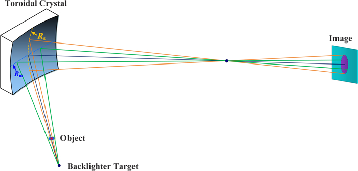
The optical path structure of the toroidal crystal x-ray imager.
| Citation: |
Haoxuan SI, Jiaqin DONG, Zhiheng FANG, Li JIANG, Shengzhen YI, Zhanshan WANG. High-resolution x-ray monochromatic imaging for laser plasma diagnostics based on toroidal crystal[J]. Plasma Science and Technology, 2023, 25(1): 015601. DOI: 10.1088/2058-6272/ac7e25

|
Monochromatic x-ray imaging is an essential method for plasma diagnostics related to density information. Large-field high-resolution monochromatic imaging of a He-like iron (Fe XXV) Kα characteristic line (6.701 keV) for laser plasma diagnostics was achieved using a developed toroidal crystal x-ray imager. A high-index crystal orientation Ge ⟨531⟩ wafer with a Bragg angle of 75.37° and the toroidal substrate were selected to obtain sufficient diffraction efficiency and compensate for astigmatism under oblique incidence. A precise offline assembly method of the toroidal crystal imager based on energy substitution was proposed, and a spatial resolution of 3–7 μm was obtained by toroidal crystal imaging of a 600 line-pairs/inch Au grid within an object field of view larger than 1.0 mm. The toroidal crystal x-ray imager has been successfully tested via side-on backlight imaging experiments of the sinusoidal modulation target and a 1000 line-pairs/inch Au grid with a linewidth of 5 μm using an online alignment method based on dual positioning balls to indicate the target and backlighter. This paper describes the optical design, adjustment method, and experimental results of a toroidal crystal system in a laboratory and laser facility.
The plasma produced by the implosion compression of laser inertial confinement fusion (ICF) radiates information-rich x-rays [1–5]. As a necessary diagnostic method, high-resolution monochromatic backlight x-ray imaging is of great significance for gaining insight into the physical processes of ICF [6–8]. The method uses x-rays generated by ultra-short and ultra-intense lasers as the backlight to probe the state of the implosion core with small-scale and high-density characteristics [9, 10]. To achieve high backlight brightness, it is necessary to focus the laser beam on the target surface in the range of tens of microns. It is difficult to obtain a sufficient illumination field of view (FOV) to cover the entire plasma region to be diagnosed using traditional small-aperture devices, such as pinhole cameras [11, 12] and grazing incidence imaging (e.g. a Kirkpatrick–Baez microscope [13–15]). Point-projection radiography has been used for large-FOV x-ray imaging in ICF experiments; however, its spatial resolution is determined by the focus size of the backlighter [16, 17]. A wire or flag target with a diameter of about 10 μm has been widely used to achieve spatial resolution of 10–20 μm [18].
The crystal's interplanar plane spacing is comparable in magnitude to the x-ray wavelength; thus, it can be used as a natural beam splitter for x-rays [19, 20]. With their optical properties of large numerical aperture and high spatial and spectral resolution, spherical crystals have been widely used in many laser facilities [21, 22]. A spherical crystal has the same radius of curvature in the meridional and sagittal directions, which causes severe astigmatism when working at oblique incidence. Therefore, the spherical crystal can only operate at near-normal incidence to achieve high-resolution imaging in two-dimensional directions [23]. The detector is placed between the meridional and sagittal focal planes to compensate for astigmatism; thus, it is not easy to achieve the best spatial resolution. Meanwhile, the lattice constants of the crystal materials are fixed. Therefore, the choice of crystal materials and orientations of x-ray imaging for some special energy points is very limited. Through systematic simulation and evaluation, Schollmeier et al [24, 25] investigated spherical crystal imaging for self-emission and backlighting measurements ranging from 1 to 25 keV. They recommended selecting high-order crystal material of InAs ⟨620⟩ for He-like iron Kα characteristic line (6.701 keV) backlighting imaging with a Bragg angle of 75.78° and a poor theoretical resolution of only 9.8 μm. Additionally, effective shielding of the background signals in near-normal incidences is a difficult technical problem to overcome.
Compared with spherical crystals, toroidal crystals have different radii of curvature in the meridian and sagittal directions, thereby eliminating severe astigmatism present in non-normal incidences and expanding the selection of crystal materials and orientations, as well as significantly improving spatial resolution [26]. Uschmann et al [27] first developed toroidal crystals of Si ⟨311⟩ and Ge ⟨311⟩ for He-like argon Kβ line (3.1 keV) imaging with an online-calibrated resolution of more than 15 μm. Jiang et al [28] reported a four-channel toroidal crystal imager of Ge ⟨400⟩ for Ti Kα line (4.51 keV) imaging with an offline calibrated resolution of 4–10 μm. Meanwhile, various types of x-ray spectrometers based on toroidal structures have been developed [29, 30]. However, there is still a lack of online diagnostic applications of toroidal crystals in laser facilities with a high spatial resolution at the 5 μm level, as well as its precise offline assembly and alignment methods. In this paper, we present a toroidal crystal x-ray imager for hydrodynamic instability growth measurement using side-on backlight imaging of a sinusoidal modulation target. The spatial resolution was further improved to a range of 3–7 μm within the FOVs of the mm class. Furthermore, precise offline assembly and alignment methods were developed.
In this work, a single crystal of Ge was used as a diffractive material due to its relatively high integrated efficiency, which is suitable for experiments in a kJ-class laser facility. The iron foil was selected as the backlight target, and a He-like iron (Fe XXV) Kα characteristic line (6.701 keV) was selected as the working energy because of higher x-ray yield compared to the Kα line (6.404 keV) and moderate penetration thickness to the side-on modulation target. The focal distances of bent-crystal imaging in the meridian and sagittal directions fm and fs can be given by the formula [31]:
| fm=Rmsinθ2;fs=Rs2sinθ | (1) |
where Rm and Rs are the radii of curvature of the substrate in the meridian and sagittal directions, respectively; θ is the Bragg angle of the crystal center. For the toroidal crystal imager, as shown in figure 1, the focal distances in two directions are equal by regulating Rm and Rs, conforming to the following formula so that the astigmatism was effectively corrected:
| RsRm=sin2θ | (2) |
Additionally, the Bragg angle of toroidal crystals should be selected in a range of 60°–80° because the incident x-rays have a certain penetration depth to the crystal material, especially for x-rays above several keV. In this work, the crystal orientation of Ge ⟨531⟩ with a lattice constant of 0.956 Å was selected, and the Bragg angle on 6.701 keV x-ray energy was 75.37°, which fits the required angular range of 60°–80° and has a higher integration efficiency than an α-quartz crystal.
After obtaining the working Bragg angle of the toroidal crystal, the ratio of the radii of curvature of the toroidal mirror in the meridian and sagittal directions is fixed. Table 1 presents the initial structure parameters of the toroidal crystal of Ge ⟨531⟩. By considering the constraints of the experiment space and the pixel size of 25 μm×25 μm of the image detector (Image Plate, FUJI Film, BAS1025 in this paper), the curvature radius Rm was set to 250 mm and magnification was about 10 times, and the limited spatial resolution determined by the detector pixel was about 5 μm at this time. The object distance u from the object to the crystal is about 133 mm, which is sufficient to place the diagnostic device and reduce the interference of splashing debris, and the image distance v was set to 1310 mm.
| Parameter | Value |
| Material | Ge ⟨531⟩ |
| θ | 75.37° |
| Rm/Rs(mm) | 250/234.05 |
| Aperture diameter (mm) | 12 |
| u (mm) | 133 |
| v (mm) | 1310 |
 DownLoad:
CSV
DownLoad:
CSV
The crystal was prepared by directly attaching a double-polished Ge wafer with a diameter of 12 mm and a thickness of about 100 μm to the toroidal substrate made of K9 glass by optical contact of the molecular force. The wafer replicated the surface shape of the toroidal substrate to ensure good replication. They were polished to obtain a roughness below 1 nm and ultrasonically cleaned to effectively strip the solvent and particles remaining on the wafer and toroidal substrate. From an instrument alignment and installation perspective, the change in the backlighter position causes deviation of the illumination area on the toroidal crystal surface, thereby reducing the brightness of the central FOV and having a serious impact on the spatial resolution. Therefore, it is essential to simultaneously ensure the position accuracy between the backlighter, object point, and toroidal crystal.
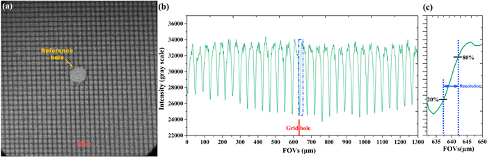
Unlike the current common installation and adjustment methods based on visible light, this paper proposes an offline assembly method with toroidal crystals using laboratory x-ray imaging to determine the best object–image relationship. Since a conventional iron x-ray tube cannot produce a He-like Kα line (6.701 keV), we use a Gd x-ray tube with very close energy (Gd Kα line 6.713 keV) as the offline source for crystal alignment. There is a difference of only about 12 eV between the two characteristic lines. Meanwhile, the Gd Kα line is completely within the spectral bandwidth of the He-like iron Kα line, which is confirmed by the later measurement results of the bent-crystal spectrometer. The focal spot of the Gd x-ray tube, with a size of about 1.0 mm×1.0 mm, was placed at about 70 mm away from the grid, with an aperture angle of about 0.014° for each object point. Figure 2(a) shows the x-ray image of a 600 line-pairs/inch grid (Gilder, G600HSS) backlit using the Gd x-ray tube after fine-tuning. The image was acquired by an x-ray charge-coupled device (CCD, Princeton Instruments: PIXIS-XO-1024B) with a resolution of 1024 pixels×1024 pixels and a pixel size of 13.5 μm×13.5 μm. A reference hole of about 150 μm in diameter was drilled in the grid to provide the position calibration of the FOVs.
Figure 2(a) shows the toroidal crystal images of the grid with a linewidth of 5–6 μm on the entire detection surface. It can be seen that the gridline clarity at four corners of figure 2(a) was worse than that at the image center, which was mainly caused by the following. Firstly, the geometric aberration increases gradually with the FOV deviation. Secondly, the imaging of the four-corners position was formed by x-ray reflection on the surface edge area of the toroidal crystal; the surface quality of the crystal edge was worse than that of the center region after optical polishing.
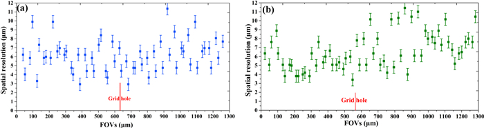
Figure 2(b) shows the intensity change in figure 2(a) in the horizontal direction (corresponding to the meridional direction). Taking the gridline as the knife-edge, the spatial resolution of the toroidal crystal in different FOVs can briefly be estimated from the intensity change. In this work, we chose an intensity change of 20%–80% (figure 2(c)) to evaluate the spatial resolution, and the measured value is shown in figure 3(a). The spatial resolution in the full FOV (about 1.3 mm) is mostly 3–7 microns. The length of the error bar was 1.35 μm, which is equivalent to the spatial resolution corresponding to one CCD pixel. The limit resolution of the toroidal crystal restricted by the CCD detector is about 2.7 μm, corresponding to two pixels. If a CCD with a smaller pixel was used, the spatial resolution could be further improved. Figure 3(b) shows the resolution calibration results in the vertical direction (corresponding to sagittal directions), which is slightly worse than that in the meridional direction but still reaches 3–7 μm within an FOV of about 1 mm. The magnification of the toroidal crystal can be calibrated by dividing the grid period in figure 2(a) by the results measured using structural equation modeling. The actual magnification and image point spacing can also be calibrated in figure 2, which are approximately 9.93 and 10.38 times in the meridian and sagittal directions, respectively.
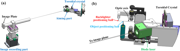
The rapid installation of the toroidal crystal in the laser facility is another important issue that needs to be considered to improve experimental efficiency. In this work, the dual positioning ball method, previously applied to the grazing Kirkpatrick-Baez microscope, was used to simultaneously indicate the ideal backlighter and object position of the toroidal crystal [32] and then realize the switch of the toroidal crystal system from the offline laboratory to the laser facility. Figure 4(a) shows the final mechanical structure of the toroidal crystal system after assembly, which includes the toroidal crystal, an aiming part, and an image-recording part. As shown in figure 4(b) of the enlarged view of the aiming part, we use an object positioning ball with a diameter of 500 μm to replace the reference hole in figure 2(a) using two orthogonal industrial cameras. Then, the optical axis of the toroidal crystal imaging was indicated by aiming at the center of the simulated sphere and toroidal crystal using an internal focusing telescope. At this time, the axis of the internal focusing telescope is equivalent to the optical axis of the toroidal crystal. Finally, the center of the backlighter positioning ball was adjusted to the axis of the internal focusing telescope. Meanwhile, the distance between the two positioning balls was aligned using a Vernier caliper to approximate 15.0 mm, consistent with the actual application conditions, where the diode laser indicates the image position to place the image plate. The two positioning balls and diode laser were connected to the toroidal crystal with the linear guides (HIWIN, MGN15P), and can be reattached with highly reproducible accuracy of about 20 μm.
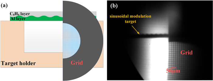
The toroidal crystal x-ray imager has been successfully tested in side-on backlight imaging of a sinusoidal modulation target in a hydrodynamic instability growth experiment in the Shenguang-Ⅱ Upgrade (SG-Ⅱ U) laser facility. The experiment's optical path was arranged according to figure 4. One of the eight laser beams (1 ns, 3ω, 800 J), with a focal spot of 300 μm diameter smoothed by a continuous-phase plate, was used to irradiate the iron foil to produce a He-like x-ray backlighter. The distance between the backlighter and the target is 15 mm, so that the aperture angle for each object point is about 0.020°. As shown in figure 5(a), a target with two layers is used in the experiments. A 20 μm thick C8H8 layer was conglutinated with a 30 μm Al layer. At the C8H8/Al interface, a perturbation of 55 μm wavelength and 1.5 μm amplitude had been machined into the Al. The C8H8 layer is nearly transparent to the 6.701 keV backlight x-rays, whereas the Al layer is opaque to it. Thus, we can obtain obvious contrast at the interface. A square grid with 1000 line-pairs/inch and a linewidth of 5 μm was placed next to the sinusoidal modulation target to calibrate the spatial resolution. Figure 5(b) shows the experimental image acquired by the image plate with a pixel size of 25 μm×25 μm. The central FOV with the best spatial resolution is the position where the grid meets the sinusoidal target. As the FOV deviates, the spatial resolution gradually deteriorates, consistent with the results of offline calibration. The effective FOV range in the horizontal direction is about 700 μm, which is mainly limited by the spectral width of the x-ray backlighter. The grid lines can be clearly observed in the effective FOV, indicating that the spatial resolution of the toroidal crystal is close to the level of the grid linewidth of about 5 μm. In addition, the aperture angle for each object point in the online experiment (0.020°) was larger than that in the offline experiment (0.014°), and the pixel size of the image plate (25 μm × 25 μm) was bigger than that of the x-ray CCD (13.5 μm × 13.5 μm); therefore, the overall spatial resolution of figure 5(b) has a certain decrease compared to figure 2(a) obtained from the offline experiment. This phenomenon can be eliminated by using an x-ray backlighter with a smaller focal spot and an image detector with a smaller pixel size in subsequent physical experiments. The actual magnification of the toroidal crystal can also be calibrated by dividing the distance between adjacent grid lines on the image by the period width of the grid. These magnifications are approximately 9.90 and 10.32 times in the meridian and sagittal directions, respectively, which are very close to the design value.
A large-field high-resolution x-ray imager of toroidal crystal Ge ⟨531⟩ was developed for backlight imaging of the He-like iron (Fe XXV) Kα characteristic line (6.701 keV). The Ge ⟨531⟩ wafer and toroidal substrate were fabricated by ultra-smooth polishing. Then, it was ultrasonically cleaned before crystal bending to ensure the surface shape. Spatial resolution of 3–7 μm within an object field larger than 1.3 mm was obtained in the offline calibration experiment. We employed a precise alignment method based on double positioning balls to reduce the online installation difficulty and improve the experimental efficiency. The side-on backlight imaging of sinusoidal modulation targets with a calibrated resolution of about 5 μm was completed by the toroidal crystal at the SG-Ⅱ U laser facility. The toroidal crystal x-ray imager can be further extended to plasma diagnostics at other x-ray energies by selecting appropriate crystal materials, crystal orientations, and substrate curvature radius.
This work is supported by National Natural Science Foundation of China (No. 11805212) and National Key Research and Development Program of China (No. 2019YFE03080200).
| [1] |
Zylstra A B et al 2021 Phys. Rev. Lett. 126 025001 doi: 10.1103/PhysRevLett.126.025001
|
| [2] |
Zylstra A B et al 2022 Nature 601 542 doi: 10.1038/s41586-021-04281-w
|
| [3] |
Kritcher A L et al 2022 Nat. Phys. 18 251 doi: 10.1038/s41567-021-01485-9
|
| [4] |
Sinars D B et al 2020 Phys. Plasmas 27 070501 doi: 10.1063/5.0007476
|
| [5] |
Yi S Z et al 2016 Rev. Sci. Instrum. 87 103501 doi: 10.1063/1.4963702
|
| [6] |
Wang F et al 2020 Matter Radiat. Extremes 5 035201 doi: 10.1063/1.5129726
|
| [7] |
Reinke M L et al 2012 Rev. Sci. Instrum. 83 113504 doi: 10.1063/1.4758281
|
| [8] |
Aglitskiy Y et al 2008 Phys. Scr. T132 014021 doi: 10.1088/0031-8949/2008/T132/014021
|
| [9] |
Batani D et al 2019 J. Fusion Energy 38 299 doi: 10.1007/s10894-019-00218-4
|
| [10] |
Maslov M et al 2012 Rev. Sci. Instrum. 83 096106 doi: 10.1063/1.4755809
|
| [11] |
Le Pape S et al 2019 High Energy Dens. Phys. 31 13 doi: 10.1016/j.hedp.2019.01.002
|
| [12] |
Zhang W H et al 2012 Nucl. Electron. Detect. Technol. 32 1027(in Chinese) doi: 10.3969/j.issn.0258-0934.2012.09.008
|
| [13] |
Yi S Z et al 2022 J. Opt. Soc. Am. B 39 A61 doi: 10.1364/JOSAB.444438
|
| [14] |
Yi S Z et al 2022 Matter Radiat. Extremes 7 015902 doi: 10.1063/5.0062758
|
| [15] |
Yi S Z et al 2018 Rev. Sci. Instrum. 89 036105 doi: 10.1063/1.5019206
|
| [16] |
May M J et al 2018 Phys. Plasmas 25 056302 doi: 10.1063/1.5015927
|
| [17] |
Blue B E, Hansen J F and Robey H F 2004 Rev. Sci. Instrum. 75 3989 doi: 10.1063/1.1787936
|
| [18] |
Tommasini R et al 2017 Phys. Plasmas 24 053104 doi: 10.1063/1.4983137
|
| [19] |
Chen G J and Hong W 2020 Adv. Opt. Mater. 8 2000984 doi: 10.1002/adom.202000984
|
| [20] |
Yang X S et al 2018 Plasma Sci. Technol. 20 124001 doi: 10.1088/2058-6272/aad177
|
| [21] |
Morace A et al 2014 Phys. Plasmas 21 102712 doi: 10.1063/1.4900867
|
| [22] |
Cao N M, Valdivia A M M and Rice J E 2016 J. Vis. Exp. 114 54408 doi: 10.3791/54408
|
| [23] |
Bitter M et al 2004 Rev. Sci. Instrum. 75 3660 doi: 10.1063/1.1791747
|
| [24] |
Schollmeier M S and Loisel G P 2016 Rev. Sci. Instrum. 87 123511 doi: 10.1063/1.4972248
|
| [25] |
Schollmeier M S et al 2015 Appl. Opt. 54 5147 doi: 10.1364/AO.54.005147
|
| [26] |
Yao T et al 2021 Chin. J. Lasers 48 2103002(in Chinese) doi: 10.3788/CJL202148.2103002
|
| [27] |
Uschmann I et al 2000 Appl. Opt. 39 5865 doi: 10.1364/AO.39.005865
|
| [28] |
Jiang C L et al 2021 Opt. Express 29 6133 doi: 10.1364/OE.415537
|
| [29] |
Bitter M et al 2018 Rev. Sci. Instrum. 89 10F118 doi: 10.1063/1.5036806
|
| [30] |
Stoupin S et al 2021 Rev. Sci. Instrum. 92 053102 doi: 10.1063/5.0043685
|
| [31] |
Pisani F et al 1999 Rev. Sci. Instrum. 70 3314 doi: 10.1063/1.1149910
|
| [32] |
Yi S Z et al 2021 High Power Laser Sci. Eng. 9 E42 doi: 10.1017/hpl.2021.30
|
| [1] | Luying NIU(牛璐莹), Hongrui CAO (曹宏睿), Kun XU(徐坤), Liqun HU(胡立群). Neutronic analysis of ITER radial x-ray camera[J]. Plasma Science and Technology, 2019, 21(2): 25601-025601. DOI: 10.1088/2058-6272/aaeba5 |
| [2] | Xinshuai YANG (杨新帅), Ruiji HU (胡睿佶), Jun CHEN (陈俊), Fudi WANG (王福地), Jia FU (符佳), Yingying LI (李颖颖), Hongming ZHANG (张洪明), Yongcai SHEN (沈永才), Xianghui YIN (尹相辉), Bo LYU (吕波), EAST team. Measurement of impurity lines with two- crystal x-ray spectrometers on EAST[J]. Plasma Science and Technology, 2018, 20(12): 124001. DOI: 10.1088/2058-6272/aad177 |
| [3] | Jun CHEN (陈俊), Ruiji HU (胡睿佶), Bo LYU (吕波), Fudi WANG (王福地), Xiaojie WANG (王晓洁), Handong XU (徐旵东), Yingying LI (李颖颖), Jia FU (符佳), Xianghui YIN (尹相辉), Dajun WU (吴大俊), Fukun LIU (刘甫坤), Qing ZANG (臧庆), Haiqing LIU (刘海庆), Yuejiang SHI (石跃江), Shifeng MAO (毛世峰), Yi YU (余羿), Baonian WAN (万宝年), Minyou YE (叶民友), Yongcai SHEN (沈永才), EAST team. Observation and characterization of the effect of electron cyclotron waves on toroidal rotation in EAST L-mode discharges[J]. Plasma Science and Technology, 2017, 19(10): 105101. DOI: 10.1088/2058-6272/aa7cec |
| [4] | WANG Yu (王玉), SU Dandan (苏丹丹), LI Yingjun (李英骏). Hydrodynamics of Exploding Foil X-Ray Lasers with Time-Dependent Ionization Effect[J]. Plasma Science and Technology, 2016, 18(12): 1181-1185. DOI: 10.1088/1009-0630/18/12/07 |
| [5] | WANG Baoqing (王保清), YI Tao (易涛), WANG Chuanke (王传珂), ZHU Xiaoli (朱效立), LI Tingshuai (李廷帅), LI Jin (李晋), LIU Shenye (刘慎业), JIANG Shaoen (江少恩), DING Yongkun (丁永坤). Design of Time-Resolved Shifted Dual Transmission Grating Spectrometer for the X-Ray Spectrum Diagnostics[J]. Plasma Science and Technology, 2016, 18(7): 781-785. DOI: 10.1088/1009-0630/18/7/14 |
| [6] | PAN Xiayun (潘夏云), WANG Fudi (王福地), ZHANG Xinjun (张新军), LYU Bo (吕波), CHEN Jun (陈俊), LI Yingying (李颖颖), FU Jia (符佳), SHI Yuejiang (石跃江), YU Yi (余羿), YE Minyou (叶民友), WAN Baonian (万宝年). Observation of Central Toroidal Rotation Induced by ICRF on EAST[J]. Plasma Science and Technology, 2016, 18(2): 114-119. DOI: 10.1088/1009-0630/18/2/03 |
| [7] | XU Xiufeng (徐修峰), LI Shiping (李世平), CAO Hongrui (曹宏睿), XIAO Rui (肖锐), et al.. A Simulation Study on the Flash X-Ray Spectra Spatial Distribution[J]. Plasma Science and Technology, 2013, 15(11): 1165-1168. DOI: 10.1088/1009-0630/15/11/16 |
| [8] | ZHANG Xiaoding (张小丁), ZHANG Jiyan (张继彦), YANG Guohong (杨国洪), et al.. A High-Efficiency X-Ray Crystal Spectrometer for X-Ray Thomson Scattering[J]. Plasma Science and Technology, 2013, 15(8): 755-759. DOI: 10.1088/1009-0630/15/8/07 |
| [9] | LU Bo (吕波), SHI Yuejiang (石跃江), WANG Fudi (王福地), WAN Baonian (万宝年), Manfred BITTER, Kenneth W. HILL, Sang-gon LEE, LI Yingying (李颖颖), FU Jia (符佳), ZHANG Jizong (张继宗), XU Jingcui (徐经翠), SHEN Yongcai. Test of a High Throughput Detector on the X-ray Crystal Spectrometer of the EAST[J]. Plasma Science and Technology, 2013, 15(2): 97-100. DOI: 10.1088/1009-0630/15/2/03 |
| [10] | HU Guangyue (胡广月), ZHANG Xiaoding (张小丁), ZHENG Jian (郑坚), LEI An-le (雷安乐), SHEN Baifei (沈百飞), XU Zhizhan, et al. Demonstration of X-ray Thomson Scattering on Shenguang-Ⅱ Laser Facility[J]. Plasma Science and Technology, 2012, 14(10): 864-870. DOI: 10.1088/1009-0630/14/10/02 |
| 1. | Wang, L., Dong, K., Zhang, Z. et al. Single-backlighter time-framed X-ray imaging diagnostics of laser plasma using a quasi-coaxial multi-channel Kirkpatrick–Baez microscope. Optics Express, 2025, 33(2): 2287-2297. DOI:10.1364/OE.547977 | |
| 2. | Du, H., Si, H., Jiang, L. et al. High-resolution, highly monochromatic, time-framed, x-ray-backlit-imaging diagnostics with dual-channel toroidal crystals. AIP Advances, 2024, 14(7): 075206. DOI:10.1063/5.0213955 | |
| 3. | Xu, H., Wen, S., Si, H. et al. Direct multiple monochromatic x-ray imaging with a pinhole array and a laterally graded multilayer mirror. Review of Scientific Instruments, 2024, 95(6): 063504. DOI:10.1063/5.0187365 | |
| 4. | Si, H., Xu, H., Du, H. et al. Areal density measurement technology for metal foils based on X-ray bent crystal imaging | [X 光弯晶成像金属薄膜面密度测量技术]. Qiangjiguang Yu Lizishu/High Power Laser and Particle Beams, 2023, 35(11): 112001. DOI:10.11884/HPLPB202335.230161 | |
| 5. | Si, H., Shan, L., Du, H. et al. High-resolution Mo Kα X-ray monochromatic backlight imaging using a toroidal crystal. Chinese Optics Letters, 2023, 21(10): 103401. DOI:10.3788/COL202321.103401 | |
| 6. | Yi, S., Du, H., Si, H. et al. A Wide-Range High-Resolution X-ray Crystal Spectrometer for Laser–Plasma Diagnostics. Photonics, 2023, 10(9): 1054. DOI:10.3390/photonics10091054 |
Supported by: Beijing Renhe Information Technology Co., Ltd. 
| Parameter | Value |
| Material | Ge ⟨531⟩ |
| θ | 75.37° |
| Rm/Rs(mm) | 250/234.05 |
| Aperture diameter (mm) | 12 |
| u (mm) | 133 |
| v (mm) | 1310 |
DownLoad:
CSV