Figure
1.
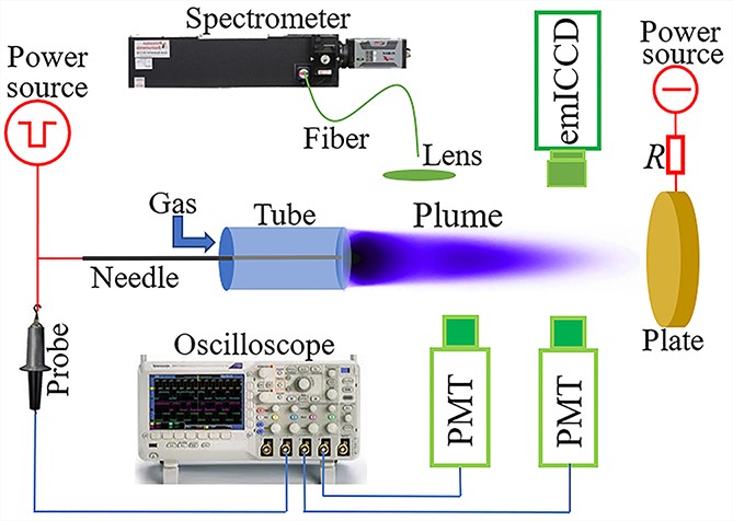
Schematic diagram of the experimental setup.
| Citation: |
Pengying JIA, Guoxin HAN, Xiupin DONG, Kaiyue WU, Junxia RAN, Xuexia PANG, Xuexue ZHANG, Jiacun WU, Xuechen LI. Influence of bias voltage and oxygen addition on the discharge aspects of a diffuse argon plume in an atmospheric pressure plasma jet[J]. Plasma Science and Technology, 2024, 26(12): 125402. DOI: 10.1088/2058-6272/ad73ab

|
A remote plasma, also referred to as a plasma plume (diffuse or filamentary), is normally formed downstream of an atmospheric pressure plasma jet. In this study, a diffuse plume is formed by increasing the bias voltage (Ub) applied to the downstream electrode of an argon plasma jet excited by a negatively pulsed voltage. The results indicate that the plume is filamentary when Ub is low, which transits to the diffuse plume with increasing Ub. The discharge initiated at the rising edge of the pulsed voltage is attributed to the diffuse plume, while that at the falling edge contributes to the filament in the plume. For the diffuse plume, the discharge intensity decreases with the increasing oxygen content (Co). Fast photography reveals that the diffuse plume results from a negative streamer, which has a dark region near the nozzle with Co = 0%. However, the dark region is absent with Co = 0.5%. From the optical emission spectrum, the electron density, electron excitation temperature, gas temperature, and oxygen atom concentration are investigated.
An atmospheric pressure plasma jet (APPJ) is capable of generating a chemically reactive plasma plume in an open space, which makes it possible to separate the plasma generation region from the application zone [1]. Due to its various advantages, such as low breakdown voltage, low gas temperature, long plasma plume, and stable operation [2, 3], the APPJ has become a promising tool in numerous potential applications, including surface modification [4, 5], biomedicine [6, 7], nanoparticle synthesis [8, 9], water activation [10, 11], disinfection [12–15], etc.
APPJs have different configurations, which can be classified into four categories [16, 17], i.e. dielectric-free electrode jets [18, 19], dielectric barrier discharge (DBD) jets [20, 21], DBD-like jets, and single-electrode jets. For DBD jets, two floating electrodes have been used to produce a longer plume at a lower operating power [22]. The APPJ is normally fed with a noble gas [16], such as helium (He) or argon (Ar) [1, 23]. With helium used as the working gas, the plasma plume is diffuse, and contracts radially with the increasing voltage amplitude, resulting in a straight filament at the center of the helium stream [24]. Hence, depending on the experimental parameters, two categories of plasma plumes, namely the diffuse plume and the filamentary plume, can be formed downstream of the APPJ. The two categories of plumes are suitable for different application scenarios; for example, the filamentary plume may distinguish itself in precisely localized deposition [25], while the diffuse plume is desirable in uniform surface treatment [26].
When using available low-cost argon, the filamentary plume is more likely to appear [27–29]. How to produce the diffuse plume in argon APPJ is a great challenge facing the researchers of low-temperature plasma. Many efforts have been made to address the challenge. For example, a diffuse argon plume has been generated under a low voltage amplitude by employing special jet configurations [2]. Moreover, the introduction of additives such as hydrogen [30], ammonia [31], acetone [32], and ethanol [33] is beneficial to the formation of the diffuse argon plume. Additionally, it has been successfully obtained with the help of seed electrons provided by the upstream discharges [34]. Recently, a viable approach to produce the diffuse argon plume has been reported, which inhibits the positive filamentary discharge with a bias electrode in the downstream region [35].
As is well known, reactive oxygen species (ROS) play an important role in the practical applications of APPJ, especially in biomedicine. In order to promote the production of ROS, oxygen is usually added to the working gas [36, 37]. It has been proven that oxygen addition remarkably affects the discharge aspects of the filamentary plume [23]. The influence of oxygen addition on the discharge aspects of the diffuse argon plume is unclear.
In this study, a diffuse argon plume is excited by a pulsed voltage with a downstream bias electrode. The discharge aspects of the diffuse argon plume are investigated with different oxygen content through an optoelectrical method, fast photography, and optical emission spectroscopy.
Figure 1 presents a schematic diagram of the experimental setup. The single-electrode APPJ is mainly composed of a 10 cm long tungsten needle with a diameter of 1 mm and a tip radius of about 500 μm, which is poised in the center of an 8 cm long quartz tube with 3 mm inner and 5 mm outer diameters. The needle tip is aligned with the tube end (nozzle). Ar and O2 with a respective purity of 99.999% are independently regulated by two mass flowmeters (Sevenstar SC200A). The volumetric content of oxygen (Co) is adjustable for the mixed working gas, which is fed into the APPJ at a total flow rate of 3 L min−1. A negatively pulsed power supply (Teslaman TP3090) is employed to drive the APPJ at a frequency of 1 kHz, a duration of 30 μs, and an amplitude of 4 kV. A copper plate with a diameter of 8.0 cm is vertically placed 4 cm away from the nozzle, which is connected via a ballast resistor (R = 1.0 MΩ) with the positive-polarity output of a direct-current power supply (Glassman EK15R40). Discharge images are captured by an electron-multiplying intensified charge-coupled device (emICCD, PI MAX4-1024EM/EMB). In addition, negatively pulsed voltage and light emissions are detected by a high-voltage probe (Tektronix P6015A) and photomultiplier tubes (PMTs; ET 9130/100B), respectively. Their waveforms are recorded by a digital oscilloscope (Tektronix DPO4054). A lens is used to image the whole plume, behind which a fiber is placed to selectively collect the light emissions and transmit to the entrance slit of the spectrometer (ACTON SP2750) equipped with a grating of 2400 grooves mm−1 and a charge coupled device (CCD) (PIXIS 400B). Hence, the optical emission spectrum can be obtained from the whole plasma plume or a spatially fixed location with a resolution of about 0.1 mm. In addition, the integration time of the CCD is 100 ms, which corresponds to 100 voltage cycles. Hence, the spectrum is time averaged.
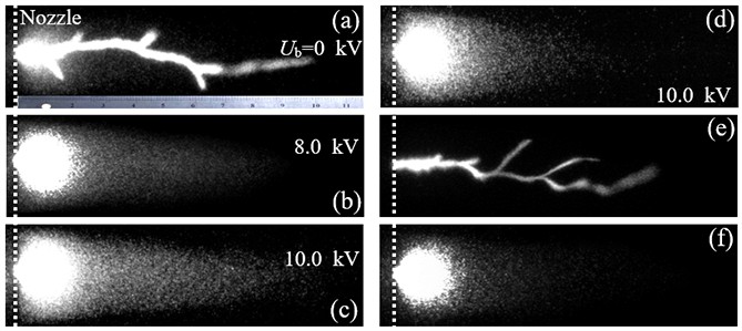
When the bias voltage (Ub) applied to the downstream plate is low (even zero), a prominent bright filament emerges in a diffuse background, as shown in figure 2(a), with an exposure time (texp) of 1 ms. This phenomenon indicates that the argon plume is filamentary with low Ub. The filament in the plume shortens with the increasing Ub, and disappears completely when increasing Ub to approximately +8 kV (figure 2(b)), leaving only the diffuse background. Hence, a diffuse plume is formed when Ub is high (figure 2(b)). Comparing figure 2(b) with figure 2(c), it can be found that the diffuse plume elongates when further increasing Ub. In addition to Ub, Co plays an important role in the length of the diffuse plume. One can see from figures 2(c) and (d) that the length of the diffuse plume decreases with increasing Co. It is worth pointing out that the effect of Co on the plume appearance (filamentary or diffuse) can be ignored. In addition, the applied electric field increases when decreasing the distance from the nozzle to the copper plate. Hence, it is helpful to produce a diffuse plume under a low Ub when the distance is decreased. However, the distance cannot be too narrow in order to prevent arcing when the diffuse plume touches the plate. Hence, a 4 cm distance is chosen.
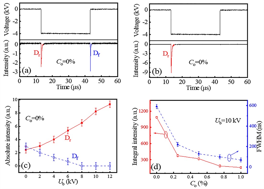
As indicated in figure 3(a), there are two discharges for the filamentary plume. The discharge initiated at the rising edge of the negative pulse voltage is defined as Dr. In addition, Df denotes that initiated at the falling voltage edge. As a comparison, Df is absent and there is only one discharge (Dr) per voltage cycle for the diffuse plume (figure 3(b)). Hence, it is clear that Df is filamentary and Dr is actually diffuse (figures 2(e) and (f) captured with texp of about 2 μs). In addition, the plasma plume should come from streamers. Hence, Df originates from some branching streamers since there are several stochastic branches [38, 39]. Moreover, Dr operates in the guided mode due to the fact that the streamer repeatedly and reproducibly propagates along a straight line [39], as will be shown later. In this meaning, Df operates in the non-guided mode. One can see from figure 3(c) that with the increasing Ub, the intensity of Dr monotonically increases, while that of Df decreases. After Ub surpasses +8 kV, the Df intensity reaches zero, suggesting the formation of a diffuse plume. Moreover, Dr is the dominant discharge for both the filamentary plume and the diffuse one because the intensity of Dr is higher than that of Df except for Ub = +0 kV. For the diffuse plume, the integral intensity and full width at half maximum (FWHM) of Dr decrease with the increasing Co (figure 3(d)), which may be a result of the plume shortening with the increasing Co (figure 2).
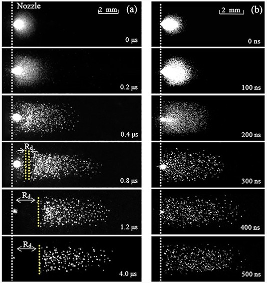
Figure 4 presents the temporal evolutions (single-shot emICCD image with texp of 20 ns) of the diffuse plume with different Co, in which time zero corresponds to the moment when the discharge first appears at the nozzle (the dotted line). For Dr, the needle is the instantaneous cathode. With Co = 0%, a spherical discharge is first initiated in the vicinity of the needle tip at 0 μs due to the non-uniform distribution of the electric field. In the spherical discharge, positive ions move towards the needle tip to produce secondary electrons through bombardment with the instantaneous cathode. Then electrons drift away from the needle tip and the spherical discharge grows in volume with the time elapsing (0.2 μs). The discharge begins to propagate downstream at 0.4 μs. It is believed that a streamer regime sets in in the APPJ [40]. Considering the polarity of the needle, it is a negative streamer in the diffuse plume. The negative streamer has a streamer head at the front and a diffuse plasma channel behind it. Moreover, the lengthening plasma channel is brighter than the propagating streamer head. At 0.8 μs, a dark region appears in the plasma channel near the jet nozzle, which is marked as Rd in figure 4. At 1.2 μs, the negative streamer reaches the plume end and Rd grows to its maximal length. Then, the streamer stops propagating, which keeps the diffuse appearance for several microseconds (4 μs) and then finally quenches. During the process mentioned above, Rd near the nozzle is always present in the discharge. Similarly, the discharge behaves as a negative streamer with Co = 0.5%. However, Rd is absent. Compared with Co = 0%, the discharge duration is remarkably decreased with Co = 0.5%. Electrons can be attached by oxygen molecules to form negative ions [41], which reduces the number of electrons and tends to quench the discharge. Hence, the durations of the streamer propagation and quenching are shortened with the increasing Co.
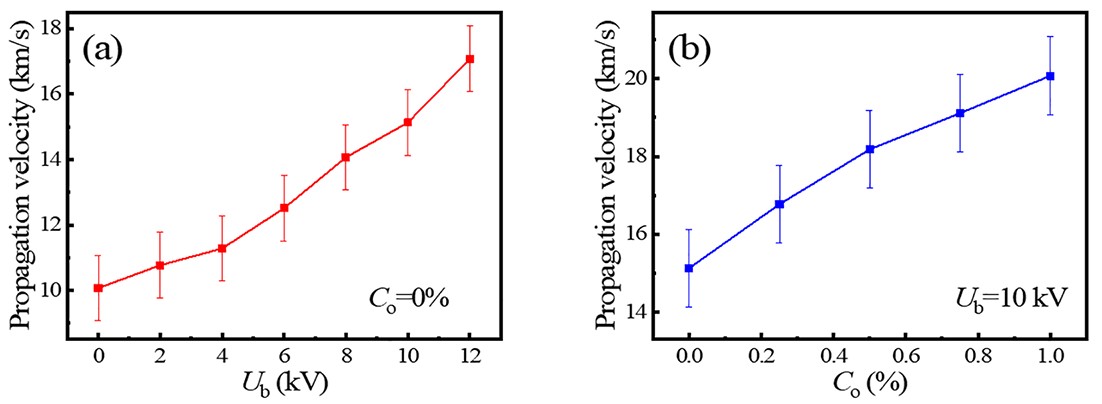
The average propagation velocity of a streamer can be measured by dividing the distance of two positions by their time lag of emission signals detected by two PMTs [42]. It can be seen from figure 5 that the average streamer velocity of Dr is in the order of 104 m s−1, which is in line with that reported by others [43, 44]. The average streamer velocity increases with the increasing Ub and Co. This phenomenon can be explained as follows. Due to the constant voltage amplitude of the pulse voltage, the applied electric field increases with the increase in Ub. As a result, electrons in the discharge acquire more energy from the increased field, leading to a higher electron drift velocity. In the negative streamer, streamer propagation is fulfilled by successive generations of electron avalanches [45]. Hence, the streamer velocity is approximately equivalent to the electron drift velocity [40, 46, 47]. As a result, the average streamer velocity increases with the increasing Ub. In contrast to argon, the field threshold to initiate a streamer is much higher in oxygen [45]. This means that the electric field to sustain a streamer propagation increases with the increasing Co. As a result, the electron drift velocity increases with the increasing Co. Consequently, the streamer velocity increases with the increasing Co.
When Co = 0%, electrons near the nozzle can hardly be attached due to the absence of electronegative oxygen molecules. Hence, the electron density is higher near the nozzle, resulting in a higher-conductivity region. Compared with other locations, the divided voltage by the plasma region with the higher-conductivity is lower, leading to a weaker-field region near the nozzle. Therefore, electrons in this region obtain a low energy that is insufficient to produce prominent emissions. As a result, Rd is formed near the nozzle with Co = 0%. As a comparison, the emission near the nozzle is clear with Co = 0.5% due to the sufficient mixed oxygen in the argon stream.
Figure 6(a) presents the optical emission spectra collected from the whole diffuse plume in the range from 300 nm to 900 nm. One can see that spectral lines of Ar I (4p→4s) are dominant, mainly including 696.5, 738.4, 750.4, 763.5, 772.4, 800.6, 801.5, 810.4, 811.5, 840.8, and 842.5 nm. In addition, there is a second positive system of N2 (C3Πu→B3Πg) with peaks at 337.1, 357.6, 380.4, and 405.8 nm. The spectra also include the rotational system of OH (A2Σ+→X2Π) with the head at 308.8 nm [48] and O I (3p3P→3s3S) at 844.6 nm [49]. The appearance of N2 (C3Πu→B3Πg), OH (A2Σ+→X2Π), and O I is attributed to the diffusion of air into the working gas [23, 50]. The intensity of OH (A2Σ+→X2Π) is stronger than that of N2 (C3Πu→B3Πg) for the diffuse plume. The reason can be analyzed as follows. The excitation energy is 4.05 eV for OH (A2Σ+) [51], and 11.0 eV for N2 (C3Πu) [52, 53]. Due to low energy of the electrons, OH (A2Σ+) is excited more effectively in the diffuse plume than N2 (C3Πu). Hence, the intensity of OH (A2Σ+→X2Π) is stronger than that of N2 (C3Πu→B3Πg). Among these spectra, OH (A2Σ+→X2Π) can be used to estimate the gas temperature (Tg) using LIFBASE software [54], as indicated in figure 6(b).
As mentioned in figure 4, the plasma channel is not dark, but brighter than the streamer head. In addition to the smaller region of the streamer head in contrast to the plasma channel, one can deduce that instead of the streamer head, the spatially integrated spectrum is mainly from the plasma channel. Now let us consider the spatially resolved spectrum. The streamer head passes through the detection position with a size of about 0.1 mm in several nanoseconds; however, the emission from the plasma channel lasts for at least several hundred nanoseconds. As a result, the spatially resolved spectrum is also mainly from the plasma channel. Accordingly, the plasma parameters estimated from the spectra should correspond to those of the plasma channel.
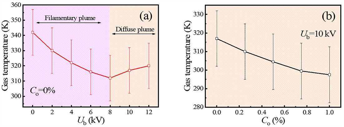
Figure 7 illustrates the averaged Tg of the plasma channel as a function of Ub and Co. It is clear that Tg first decreases, reaching a minimum at the transition to the diffuse plume, and then increases with the increasing Ub. Furthermore, Tg monotonously decreases with the increasing Co. The variation of Tg can be discussed as follows. Compared to the diffuse discharge, the filamentary one has a higher Tg due to its constricted channel [30, 33, 55]. As mentioned above, the filamentary Df weakens as Ub increases. Hence, Tg of the filamentary plume decreases with the increasing Ub. After the transition to the diffuse plume, when further increasing Ub, Dr strengthens (figure 3(c)), and the electron density and electron temperature increase in the plasma channel (as will be shown later). As a result, more energy is transported to heavy particles by electrons through collisions. Therefore, Tg increases with the increasing Ub. Consequently, with the increasing Ub, Tg first decreases, and then increases after the transition to the diffuse plume. Generally speaking, in the plasma channel there are electrons, positive ions, and negative oxygen ions besides neutral particles. Compared with heavy ions, much more energy is obtained by electrons. Hence, electrons are warm, while neutral particles and ions are cool in the plasma channel. Through inelastic collisions with electrons, energy is transported from electrons to neutral particles. With increasing Co, more electrons are attached by oxygen molecules in the plasma channel, leading to a reduction in electrons, as will be shown later. The number decrement in electrons leads to less energy being transported to heavy particles. Hence, Tg monotonously decreases with the increasing Co.
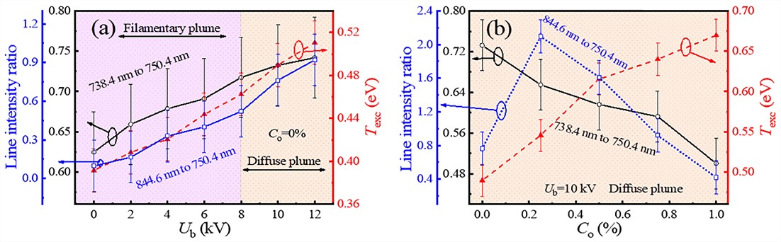
The intensity ratio of spectral lines (738.4 nm to 750.4 nm) can be thought of as an indicator of electron density [56–58]. From an actinometry method, the intensity ratio of spectral lines (844.6 nm to 750.4 nm) is directly proportional to the oxygen atom concentration [23, 41, 59]. Moreover, the electron excitation temperature (Texc) can be obtained from the Boltzmann plot method [29, 60]. Figure 8 presents the line intensity ratios and Texc averaged in the plasma channel as functions of Ub and Co. It can be inferred that the average electron density, Texc, and oxygen atom concentration increase as Ub increases. With increasing Co, the average electron density and Texc in the plasma channel monotonously decrease and increase, respectively. The average oxygen atom concentration in the plasma channel first increases, and then decreases after reaching a maximum.
As mentioned in figure 3(c), Dr is the dominant discharge for both the filamentary plume and the diffuse one. As Ub increases, the electric field of Dr increases, leading to an increment in the discharge intensity, electron density, and Texc of Dr. Therefore, both the electron density and Texc increase with the increasing Ub for the diffuse plume. For the filamentary plume, more energetic electrons are left by Dr to help the next discharge [1, 61], leading to a higher electron density and Texc of Df. Consequently, the electron density and Texc keep increasing as Ub increases. This effect causes more oxygen molecules to be decomposed. Hence, the oxygen atom concentration also increases with the increasing Ub. With the increase of Co, more electrons are attached by electronegative species, for example, O2, O, etc. As a result, the electron density monotonously decreases with the increasing Co. Low-energy electrons attach easier in contrast to energetic electrons; therefore, more low-energy electrons are attached, which leads to a higher Texc with the increasing Co. In addition, the oxygen atom concentration as a function of Co can be attributed to the competing effects of oxygen molecules, which facilitate the generation of oxygen atoms through the decomposition reaction and restrain atomic oxygen production due to electron attachment. It seems that the facilitating effect is dominant with low Co, and the restraining effect prevails with high Co.
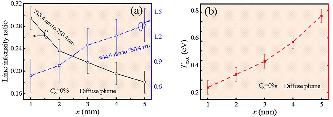
One can see from figure 9 that when increasing the distance from the nozzle (x = 0), the electron density decreases in the plasma channel, while Texc and the oxygen atom concentration increase in the plasma channel. The reason can be discussed as follows. It is believed that more oxygen molecules are diffused into the argon stream with the increasing distance, which leads to the decreasing electron density and the increasing Texc due to electron attachment as mentioned before. In general, Co through diffusion is still low in the argon stream. Under such conditions, more oxygen molecules facilitate the production of oxygen atoms. Hence, the oxygen atom concentration increases with the increasing distance from the jet nozzle.
In summary, by increasing the Ub applied to the downstream biased electrode, a diffuse plume has been obtained in an argon APPJ excited by a negatively pulsed voltage. The main conclusions are given as follows.
(1) Fast photography reveals that Dr corresponds to a diffuse negative streamer, while Df is a filamentary positive streamer.
(2) With increasing Ub, the Dr intensity increases and the Df intensity decreases to zero. With increasing Co, the Dr intensity decreases.
(3) The diffuse plume possesses Rd with Co = 0%, while Rd is absent with Co = 0.5%.
(4) The streamer propagation velocity of the diffuse plume increases with increasing Ub or Co.
(5) Optical emission spectroscopy indicates that the electron density, Texc, and oxygen atom concentration in the plasma channel increase as Ub increases. When increasing Co, the electron density and Texc in the plasma channel monotonously decrease and increase, respectively. However, the oxygen atom concentration in the plasma channel first increases, after reaching a maximum, and then decreases. In addition, in the plasma channel, the electron density decreases, while Texc and the oxygen atom concentration increase with the increasing distance from the nozzle.
(6) Qualitative explanations are given about the dis-charge aspects of the diffuse plume.
This work was supported by National Natural Science Foundation of China (Nos. 12375250, 11875121, 51977057 and 11805013), the Natural Science Foundation of Hebei Province (Nos. A2020201025 and A2022201036), Hebei Province Optoelectronic Information Materials Laboratory Performance Subsidy Fund Project (No. 22567634H), Funds for Distinguished Young Scientists of Hebei Province (No. A2012201045), the Natural Science Interdisciplinary Research Program of Hebei University (Nos. DXK201908 and DXK202011), and the Post-graduate’s Innovation Fund Project of Hebei University (No. HBU2022bs004).
| [1] |
Li X C et al 2019 Plasma Sources Sci. Technol. 28 055006 doi: 10.1088/1361-6595/aaffff
|
| [2] |
Chen M et al 2024 Appl. Phys. Lett. 124 214102 doi: 10.1063/5.0209280
|
| [3] |
Nguyen D B et al 2023 Plasma Chem. Plasma Process. 43 1475 doi: 10.1007/s11090-023-10404-0
|
| [4] |
Cui X L et al 2018 Vacuum 151 15 doi: 10.1016/j.vacuum.2018.01.042
|
| [5] |
Bedrouni F et al 2023 Phys. Scr. 98 085608 doi: 10.1088/1402-4896/ace856
|
| [6] |
Babaeva N Y and Naidis G V 2018 Trends Biotechnol. 36 603 doi: 10.1016/j.tibtech.2017.06.017
|
| [7] |
Athanasopoulos D et al 2018 Appl. Phys. Lett. 112 213703 doi: 10.1063/1.5027901
|
| [8] |
Fang J H et al 2015 Int. J. Hydrog. Energy 40 6165 doi: 10.1016/j.ijhydene.2015.02.134
|
| [9] |
Chen G L et al 2021 ACS Appl. Mater. Interfaces 13 45566 doi: 10.1021/acsami.1c13480
|
| [10] |
Chen Z Y et al 2018 J. Phys. D: Appl. Phys. 51 325201 doi: 10.1088/1361-6463/aad0eb
|
| [11] |
Xu H et al 2018 Phys. Plasmas 25 13520 doi: 10.1063/1.5016510
|
| [12] |
Zhang J et al 2022 Appl. Phys. Lett. 120 264102 doi: 10.1063/5.0096605
|
| [13] |
Guo Y T et al 2021 Appl. Phys. Lett. 119 090601 doi: 10.1063/5.0064020
|
| [14] |
Ghimire B et al 2022 J. Phys. D: Appl. Phys. 55 125207 doi: 10.1088/1361-6463/ac43d9
|
| [15] |
Das S et al 2024 Phys. Scr. 99 025601 doi: 10.1088/1402-4896/ad1869
|
| [16] |
Lu X, Laroussi M and Puech V 2012 Plasma Sources Sci. Technol. 21 034005 doi: 10.1088/0963-0252/21/3/034005
|
| [17] |
Deepak G D 2022 Eur. Phys. J. Appl. Phys. 97 39 doi: 10.1051/epjap/2022210275
|
| [18] |
Jia P Y et al 2023 IEEE Trans. Radiat. Plasma Med. Sci. 7 203 doi: 10.1109/TRPMS.2022.3195886
|
| [19] |
Jia P Y et al 2023 Chin. Phys. B 32 085202 doi: 10.1088/1674-1056/acbde9
|
| [20] |
Deepak G D, Joshi N K and Prakash R 2018 AIP Adv. 8 055321 doi: 10.1063/1.5023072
|
| [21] |
Deepak G D et al 2016 Laser Part. Beams 34 615 doi: 10.1017/S0263034616000501
|
| [22] |
Deepak G D et al 2017 Rev. Sci. Instrum. 88 013505 doi: 10.1063/1.4974101
|
| [23] |
Chen J Y et al 2022 Chin. Phys. B 31 065205 doi: 10.1088/1674-1056/ac601a
|
| [24] |
Tsai T C and Staack D 2011 Plasma Process. Polym. 8 523 doi: 10.1002/ppap.201000171
|
| [25] |
Wu K Y et al 2022 Plasma Process. Polym. 19 2200003 doi: 10.1002/ppap.202200003
|
| [26] |
Khatami S et al 2023 Plasma Chem. Plasma Process. 43 1131 doi: 10.1007/s11090-023-10354-7
|
| [27] |
Li X C et al 2020 Plasma Sources Sci. Technol. 29 065015 doi: 10.1088/1361-6595/ab6362
|
| [28] |
Wu J C et al 2021 Phys. Plasmas 28 073501 doi: 10.1063/5.0047988
|
| [29] |
Wu J C et al 2023 Plasma Process. Polym. 20 2200188 doi: 10.1002/ppap.202200188
|
| [30] |
Wu S et al 2013 J. Appl. Phys. 114 043301 doi: 10.1063/1.4816318
|
| [31] |
Kloc P et al 2010 J. Phys. D: Appl. Phys. 43 345205 doi: 10.1088/0022-3727/43/34/345205
|
| [32] |
Urabe K, Yamada K and Sakai O 2011 Jpn. J. Appl. Phys. 50 116002 doi: 10.1143/JJAP.50.116002
|
| [33] |
Xia W J et al 2018 Plasma Sources Sci. Technol. 27 055001 doi: 10.1088/1361-6595/aabdc1
|
| [34] |
Li J et al 2017 J. Appl. Phys. 122 013301 doi: 10.1063/1.4989975
|
| [35] |
Zhao N et al 2022 J. Phys. D: Appl. Phys. 55 015203 doi: 10.1088/1361-6463/ac27d5
|
| [36] |
Ghimire B et al 2018 Appl. Phys. Lett. 113 194101 doi: 10.1063/1.5055592
|
| [37] |
Brisset A et al 2021 J. Phys. D: Appl. Phys. 54 285201 doi: 10.1088/1361-6463/abefec
|
| [38] |
Stepanova O et al 2020 Jpn. J. Appl. Phys. 59 SHHC03 doi: 10.35848/1347-4065/ab75b4
|
| [39] |
Hofmann S, Sobota A and Bruggeman P 2012 IEEE Trans. Plasma Sci. 40 2888 doi: 10.1109/TPS.2012.2211621
|
| [40] |
Lu X P and Laroussi M 2006 J. Appl. Phys. 100 063302 doi: 10.1063/1.2349475
|
| [41] |
Jia P Y et al 2021 Plasma Sources Sci. Technol. 30 095021 doi: 10.1088/1361-6595/abde51
|
| [42] |
Karakas E and Laroussi M 2010 J. Appl. Phys. 108 063305 doi: 10.1063/1.3483935
|
| [43] |
Xiong Z et al 2010 J. Appl. Phys. 108 103303 doi: 10.1063/1.3511448
|
| [44] |
Shao T et al 2014 EPL 107 65004 doi: 10.1209/0295-5075/107/65004
|
| [45] |
Raizer Y P 1991 Gas Discharge Physics (Berlin: Springer
|
| [46] |
Ye R B and Zheng W 2008 Appl. Phys. Lett. 93 071502 doi: 10.1063/1.2972119
|
| [47] |
Xiong Q et al 2009 J. Appl. Phys. 106 083302 doi: 10.1063/1.3239512
|
| [48] |
Wu K Y et al 2023 High Volt. 8 1161 doi: 10.1049/hve2.12327
|
| [49] |
Greb A et al 2014 Appl. Phys. Lett. 105 234105 doi: 10.1063/1.4903931
|
| [50] |
Xiong Q et al 2010 J. Phys. D: Appl. Phys. 43 415201 doi: 10.1088/0022-3727/43/41/415201
|
| [51] |
Chakrabarti K, Laporta V and Tennyson J 2019 Plasma Sources Sci. Technol. 28 085013 doi: 10.1088/1361-6595/ab364c
|
| [52] |
Choi J H et al 2006 Plasma Sources Sci. Technol. 15 416 doi: 10.1088/0963-0252/15/3/017
|
| [53] |
Shao T et al 2015 IEEE Trans. Plasma Sci. 43 726 doi: 10.1109/TPS.2014.2359515
|
| [54] |
Li Q et al 2012 Appl. Phys. Lett. 100 133501 doi: 10.1063/1.3698135
|
| [55] |
Xia W J et al 2019 Plasma Sources Sci. Technol. 28 125005 doi: 10.1088/1361-6595/ab5168
|
| [56] |
Zhu X M et al 2009 J. Phys. D: Appl. Phys. 42 142003 doi: 10.1088/0022-3727/42/14/142003
|
| [57] |
Zhu X M and Pu Y K 2010 J. Phys. D: Appl. Phys. 43 403001 doi: 10.1088/0022-3727/43/40/403001
|
| [58] |
Wu K Y et al 2020 Phys. Plasmas 27 082308 doi: 10.1063/5.0002697
|
| [59] |
Li S Z et al 2009 Appl. Phys. Lett. 94 111501 doi: 10.1063/1.3099339
|
| [60] |
Horvath G et al 2013 IEEE Trans. Plasma Sci. 41 613 doi: 10.1109/TPS.2012.2234140
|
| [61] |
Wu S et al 2013 Phys. Plasmas 20 023503 doi: 10.1063/1.4791652
|
| [1] | Fengwu LIU, Lanlan NIE, Xinpei LU. On the green aurora emission of Ar atmospheric pressure plasma[J]. Plasma Science and Technology, 2022, 24(5): 055408. DOI: 10.1088/2058-6272/ac52ec |
| [2] | Bo ZHANG (张波), Ying ZHU (朱颖), Feng LIU (刘峰), Zhi FANG (方志). The influence of grounded electrode positions on the evolution and characteristics of an atmospheric pressure argon plasma jet[J]. Plasma Science and Technology, 2017, 19(6): 64001-064001. DOI: 10.1088/2058-6272/aa629f |
| [3] | CHANG Zhengshi (常正实), YAO Congwei (姚聪伟), ZHANG Guanjun (张冠军). Non-Thermal Equilibrium Atmospheric Pressure Glow-Like Discharge Plasma Jet[J]. Plasma Science and Technology, 2016, 18(1): 17-22. DOI: 10.1088/1009-0630/18/1/04 |
| [4] | CHEN Bingyan (陈秉岩), ZHU Changping (朱昌平), CHEN Longwei (陈龙威), FEI Juntao (费峻涛), GAO Ying (高莹), WEN Wen (文文), SHAN Minglei (单鸣雷), REN Zhaoxing (任兆杏). Atmospheric Pressure Plasma Jet in Organic Solution: Spectra, Degradation Effects of Solution Flow Rate and Initial pH Value[J]. Plasma Science and Technology, 2014, 16(12): 1126-1134. DOI: 10.1088/1009-0630/16/12/08 |
| [5] | ZHOU Yongjie(周永杰), YUAN Qianghua(袁强华), WANG Xiaomin(王晓敏), YIN Guiqin(殷桂琴), DONG Chenzhong(董晨钟). Optical Spectroscopic Investigation of Ar/CH 3 OH and Ar/N 2 /CH 3 OH Atmospheric Pressure Plasma Jets[J]. Plasma Science and Technology, 2014, 16(2): 99-103. DOI: 10.1088/1009-0630/16/2/03 |
| [6] | JIN Ying (金英), REN Chunsheng (任春生), YANG Liang (杨亮), ZHANG Jialiang (张家良), et al.. Atmospheric Pressure Plasma Jet in Ar and O 2 /Ar Mixtures: Properties and High Performance for Surface Cleaning[J]. Plasma Science and Technology, 2013, 15(12): 1203-1208. DOI: 10.1088/1009-0630/15/12/08 |
| [7] | LI Zhanguo (李战国), LI Ying (李颖), CAO Peng (曹鹏), ZHAO Hongjie (赵红杰). Surface Decontamination of Chemical Agent Surrogates Using an Atmospheric Pressure Air Flow Plasma Jet[J]. Plasma Science and Technology, 2013, 15(7): 696-701. DOI: 10.1088/1009-0630/15/7/17 |
| [8] | WEN Xueqing (闻雪晴), XIN Yu (信裕), FENG Chunlei (冯春雷), DING Hongbin (丁洪斌). Electron Energy and the Effective Electron Temperature of Nanosecond Pulsed Argon Plasma Studied by Global Simulations Combined with Optical Emission Spectroscopic Measurements[J]. Plasma Science and Technology, 2012, 14(1): 40-47. DOI: 10.1088/1009-0630/14/1/10 |
| [9] | FEI Xiaomeng(费小猛), Shin-ichi KURODA, Yuki KONDO, Tamio MORI, Katsuhiko HOSOI. Influence of Additive Gas on Electrical and Optical Characteristics of Non- equilibrium Atmospheric Pressure Argon Plasma Jet[J]. Plasma Science and Technology, 2011, 13(5): 575-582. |
| [10] | QIAN Muyang(钱沐杨), REN Chunsheng(任春生), WANG Dezhen(王德真), FENG Yan(冯岩), ZHANG Jialiang(张家良). Atmospheric Pressure Cold Argon/Oxygen Plasma Jet Assisted by Preionization of Syringe Needle Electrode[J]. Plasma Science and Technology, 2010, 12(5): 561-565. |
Supported by: Beijing Renhe Information Technology Co., Ltd. 
 DownLoad: