Figure
1.
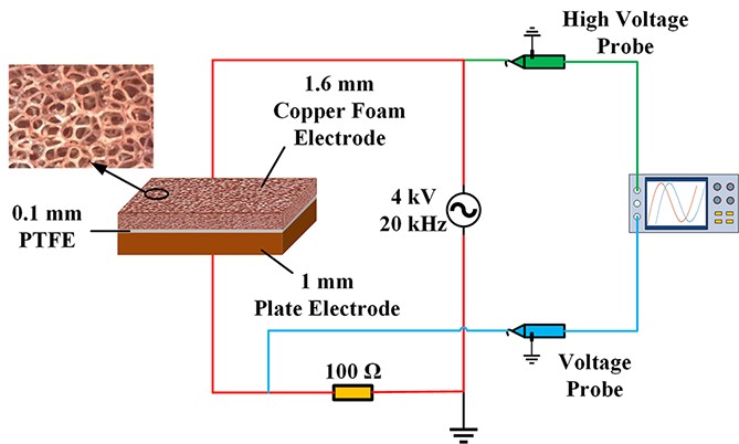
The schematic diagram of the experimental system.
| Citation: |
Shuai XU, Wenzheng LIU, Jiaying QIN, Yiwei SUN, Xitao JIANG, Qi QI. Study of three-dimensional spatial diffuse discharge in contact electrode structure applied to air purification[J]. Plasma Science and Technology, 2024, 26(10): 105401. DOI: 10.1088/2058-6272/ad5ca0

|
In this work, based on the role of pre-ionization of the non-uniform electric field and its effect of reducing the collisional ionization coefficient, a diffuse dielectric barrier discharge plasma is formed in the open space outside the electrode structure at a lower voltage by constructing a three-dimensional non-uniform spatial electric field using a contact electrode structure. The air purification study is also carried out. Firstly, a contact electrode structure is constructed using a three-dimensional wire electrode. The distribution characteristics of the spatial electric field formed by this electrode structure are analyzed, and the effects of the non-uniform electric field and the different angles of the vertical wire on the generation of three-dimensional spatial diffuse discharge are investigated. Secondly, the copper foam contact electrode structure is constructed using copper foam material, and the effects of different mesh sizes on the electric field distribution are analyzed. The results show that as the mesh size of the copper foam becomes larger, a strong electric field region exists not only on the surface of the insulating layer, but also on the surface of the vertical wires inside the copper foam, i.e., the strong electric field region shows a three-dimensional distribution. Besides, as the mesh size increases, the area of the vertical strong electric field also increases. However, the electric field strength on the surface of the insulating layer gradually decreases. Therefore, the appropriate mesh size can effectively increase the discharge area, which is conducive to improving the air purification efficiency. Finally, a highly permeable stacked electrode structure of multilayer wire-copper foam is designed. In combination with an ozone treatment catalyst, an air purification device is fabricated, and the air purification experiment is carried out.
Non-equilibrium plasma is widely used in the fields of air purification and material treatment due to its low temperature and active chemical properties [1–6]. For plasma air purification, generating plasma with better dispersion and higher concentration of active particles in atmospheric pressure air is more important in the application. In addition, due to the higher discharge voltage in atmospheric air, the power required for discharge is higher. Reducing the discharge voltage is conducive to reducing the power, the difficulty of power supply design, and the cost of the power supply.
In atmospheric pressure air environment, the electron avalanche develops violently due to the short mean free path of the electrons and the high discharge voltage. As a result, the discharge is highly susceptible to conversion into a filamentary discharge. Currently, some research groups have investigated the formation of glow discharges under atmospheric pressure conditions using dielectric barrier discharge or nanosecond pulses [7–14]. Massines and Gouda pointed out that the necessary condition for the formation of glow discharge is that a large number of seed electrons must be present before the breakdown to form multi electron avalanches, while effectively reducing the spatial electric field to obtain more slowly growing small electron avalanche [15]. Fang et al achieved atmospheric pressure air glow discharge at 6.5 kV and 50 Hz by changing the arrangement of the barrier layer and inserting an additional fine wire mesh between the electrode and the PET film [7]. It has been concluded that the wire mesh plays an important role in providing initial electrons by generating corona discharge. Buchta et al similarly formed atmospheric pressure glow discharge by adding a mesh electrode between the electrode and the dielectric layer, and suggesting that the high resistance of the mesh electrode may suppress the generation of filamentary discharge [16]. Wang et al used mesh electrode and PET film to achieve a uniform discharge in air. The results show that the use of mesh electrode enhances the electric field strength in the vicinity of the PET film, which causes the region to generate the discharge first and provide seed electrons to the space, thus reducing the discharge voltage across the air gap and suppressing filamentary discharge [17]. However, most of the studies still have limitations such as discharge confined between two electrodes, small discharge gap, high discharge voltage and complex power supply, which are not conducive to large-scale applications.
In our previous studies, we used contact electrode structures to form a non-uniform electric field distribution, which facilitates the generation of a stable diffuse discharge plasma on the surface of the insulating layer at lower voltages [18–20]. On this basis, a contact electrode structure constructed using copper foam material with a smaller wire diameter is proposed in this paper. The contact electrode structure consisting of microelectrode is capable of generating diffuse discharge in open space [21, 22]. Furthermore, the electrode structure proposed in this paper forms a three-dimensional spatial diffuse discharge at low voltage by constructing a three-dimensional spatial non-uniform electric field in the copper foam meshes. In addition, a multilayer wire-copper foam stacked electrode structure is further designed for air purification application. The electrode structure has good permeability in the direction perpendicular to the surface of the copper foam, which is more conducive to the contact between plasma in copper foam meshes and air pollutants, and improves the treatment efficiency. The air purification experiment was carried out according to the above theoretical basis.
The experimental system is shown in figure 1, including a high-frequency AC power supply, discharge electrodes and a measurement system. The high-frequency AC power supply is a homemade transformer feedback oscillator circuit, which can output a sine wave with voltage of 0–4 kV and frequency of 20 kHz. This circuit has the characteristics of low cost, high stability and high output power. The measurement system mainly consists of Tektronix High Voltage Probe P6015A for measuring the voltage U between the discharge electrodes, Tektronix Voltage Probe TPP0101 for measuring the voltage of a 100 Ω resistor, the value of which is used to calculate the discharge current I, and Tektronix Digital Oscilloscope TDS1012B-SC for recording the voltage waveforms. The discharge is documented photographically using a Nikon D750 digital camera with a macro lens.
Foam metal is a special metal material that contains a large number of connected foam micropores inside. It has a high air permeability, with a porosity of 60%–98% and a through-hole rate of 98% or more. Its internal holes are randomly arranged, and the airflow flows randomly inside the material, which is conducive to prolonging the airflow passage time. The contact electrode structure is constructed by two-dimensional electrodes, where the discharge is confined to the electrode surface only and does not diffuse well into space. Therefore, in this study, copper foam material is used to construct a copper foam contact electrode structure. The electrode structure has a large number of tiny three-dimensional meshes inside the copper foam above the surface of the insulating layer, which can make the discharge better diffuse to the space.
The copper foam structure is simplified to construct a three-dimensional crossed three-wire contact electrode structure, and its spatial electric field distribution and discharge characteristics are analyzed.
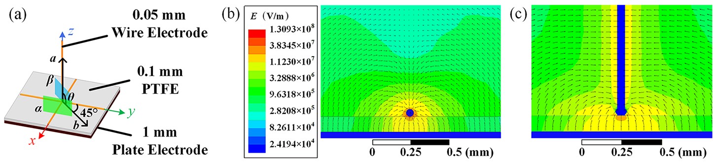
Figure 2(a) shows a schematic diagram of the three-dimensional crossed three-wire contact electrode structure. The diameter of the wire electrodes is 0.05 mm and the three wire electrodes cross each other perpendicularly in space. The insulating layer is made of polytetrafluoroethylene (PTFE) with a thickness of 0.1 mm. The lowest layer is a plate electrode with a thickness of 1 mm. The electric field simulation of this electrode structure is carried out by ANSOFT MAXWELL 3D simulation software. The wire electrodes are grounded and a 2 kV potential is applied to the plate electrode during the simulation.
Figure 2(b) shows the electric field distribution in cross-section α at a distance of 0.5 mm from the y-z plane, which reflects the electric field distribution near the horizontal metal wire electrode in contact with the insulation layer. It can be seen that the electric field strength is the strongest at the edge of the horizontal wire electrode in contact with the insulating layer. Moreover, since the diameter of the horizontal wire electrode is only 0.05 mm, the electric field lines departing from the plate electrode through the insulating layer can be wrapped around the top of this electrode, so that a strong electric field region with an electric field strength of more than 3×10⁶ V/m wraps around the entire horizontal wire electrode. In addition, it can be observed that the electric field strength gradually decreases along the opposite direction of the electric field lines. This non-uniform electric field reduces the collisional ionization coefficient along the development path of the electron avalanche, which contributes to limiting the growth of the electron density and suppressing filamentary discharge. Moreover, the electrode structure will first discharge in a strong electric field region with a small gap near the horizontal wire electrode, and its generated plasma can provide seed electrons to an adjacent region with a weaker electric field by diffusion. This allows large-area discharge to be generated at a lower voltage, which reduces the electric field strength and facilitates the suppression of filamentary discharge. Figure 2(c) shows the electric field distribution in cross-section β at an angle of 45° to the y-z plane, which reflects the electric field distribution around the wire electrode perpendicular to the insulating layer. It can be seen that the electric field lines departing from the plate electrode can also reach the surface of the vertical wire electrode, so that the electrode is also wrapped by a strong electric field region, and the electric field strength on its surface is greater than 1×10⁷ V/m. The formation of this vertical strong electric field region is conducive to the development of the discharge in the vertical direction of space and increasing the discharge area, which is a more important feature of this electrode structure.
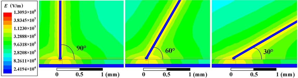
Then, the angle θ between the vertical wire electrode and the insulating layer is changed. Through simulation comparison, when the angle θ is located at the position shown in figure 2(a), the different angles of the vertical wire have the greatest influence on the electric field distribution. Therefore, this case is analyzed in this study, and the simulation results of the electric field in cross-section β are shown in figure 3.
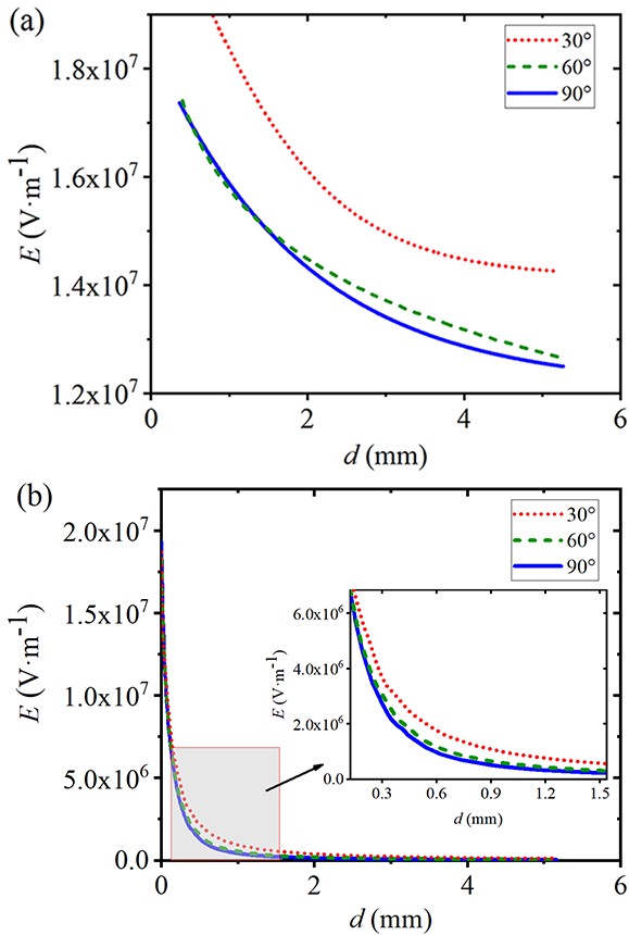
It can be observed that the area of the strong electric field in the space between the vertical wire electrode and the insulating layer increases as the angle θ decreases. Figure 4 shows the variation curves of the electric field strength along line segment a and line segment b. As can be seen from the curves, the electric field strengths on both the surface of the vertical wire electrode and the surface of the insulating layer increase with the decrease of the angle θ, which is favorable for the diffusion of the discharge along the surface of the vertical wire electrode and the surface of the insulating layer. However, it is conceivable that as the angle θ decreases, the spatial electric field strength increases and the electric field inhomogeneity decreases. In addition, there is still a certain distance between the electrodes, which makes the electron avalanche develop more violently, and the discharge will be easily converted to filamentary discharge. Therefore, the angle should not be too small.
In summary, it can be observed that the electrode structure forms a three-dimensional non-uniform spatial electric field on the upper surface of the insulating layer, which makes it possible to form a three-dimensional spatial diffuse discharge in the open space outside the electrode structure.
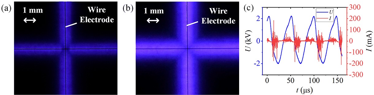
Figure 5 shows a top view of the discharge phenomenon when the electrode structure has only horizontal wire electrode, and its corresponding voltage-current waveform. When the voltage is 1.2 kV, a diffuse discharge near both sides of the wire electrode forms. When the voltage is 2 kV, as can be seen in figure 5(b), it has been able to form a diffuse discharge area of about 1 mm wide near each side of the wire electrode, and the width of the discharge area is 40 times the diameter of the wire electrode. Figure 5(c) shows the voltage-current waveform at voltage of 2 kV. Because this electrode structure is capacitively loaded, there is a capacitive current in the current waveform. Besides, there are multiple current pulses in every half cycle, the amplitude of which is about 100 mA on average.
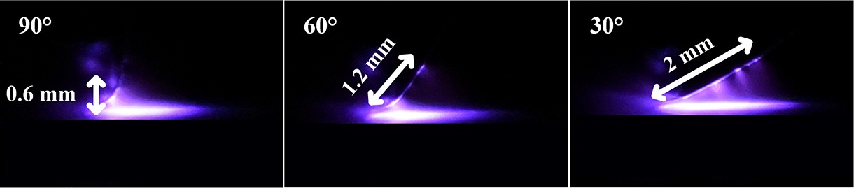
Figure 6 shows the discharge near the vertical wire electrode at different angles θ after adding the vertical wire electrode. It can be observed that the discharge on the surface of the vertical wire electrode is gradually enhanced as the angle θ decreases, and the length of the discharge increases from 0.6 mm to 2 mm. As the angle decreases, the discharge is gradually generated in the space between the vertical wire electrode and the insulating layer. At θ = 30°, a large area of diffuse discharge is formed in the space between the vertical wire electrode and the insulating layer. It follows that the three-dimensional non-uniform spatial electric field formed by using a three-dimensional electrode structure is conducive to the expansion of the discharge area and the formation of a large-area diffuse discharge in space.
In order to further analyze the properties of the copper foam structure, a multilayer three-dimensional mesh contact electrode structure is constructed in this section and compared with a single-layer two-dimensional mesh contact electrode structure to analyze the spatial electric field distribution and discharge characteristics.
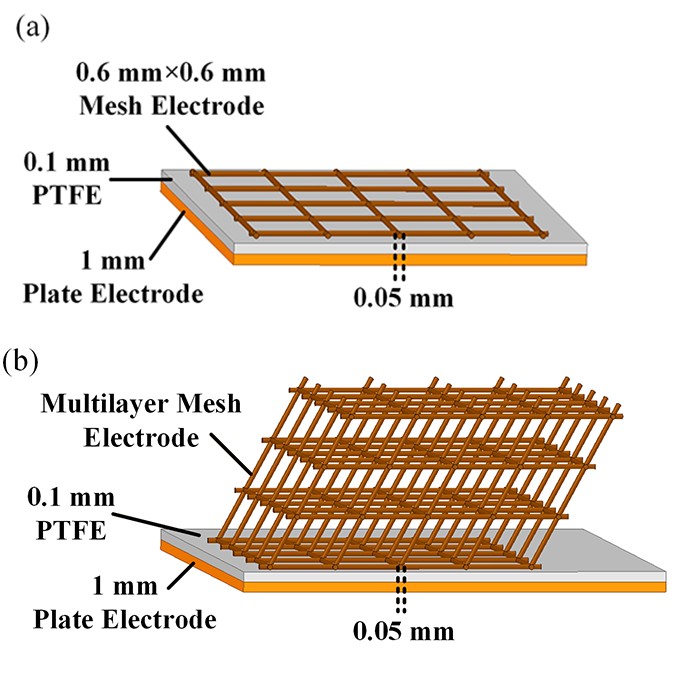
Figure 7(a) shows a single-layer two-dimensional mesh contact electrode structure with a square mesh of 0.6 mm side length and 0.05 mm filament diameter. Figure 7(b) shows a multilayer three-dimensional mesh contact electrode structure with the same mesh parameters as above and a vertical wire electrode tilt angle θ of 45°. The thickness of the insulating layer is 0.1 mm for both electrode structures. In the simulation, both mesh electrodes are grounded and the plate electrodes are applied with 2 kV potential.
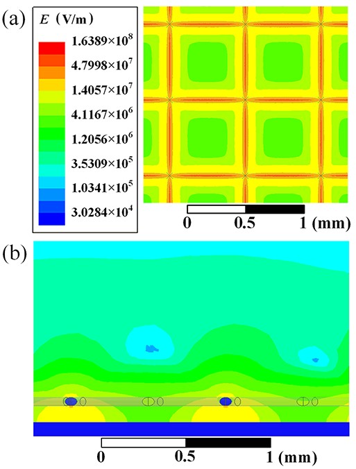
Figure 8 shows the electric field distribution characteristics of the single-layer two-dimensional mesh contact electrode structure. From figure 8(a), it can be seen that the electric field strength at the point of contact between the mesh electrode and the insulating layer is the largest, while the smallest electric field strength at the center of the mesh hole also reaches 2.39×10⁶ V/m. A non-uniform electric field is formed within each mesh on the surface of the insulating layer, which facilitates the limitation of electron avalanche. As can be seen in figure 8(b), the strong electric field region with electric field strength of E > 3×10⁶ V/m wraps around the surface of the mesh electrode, but the longest extension of the strong electric field region in the vertical direction is only about 0.1 mm.
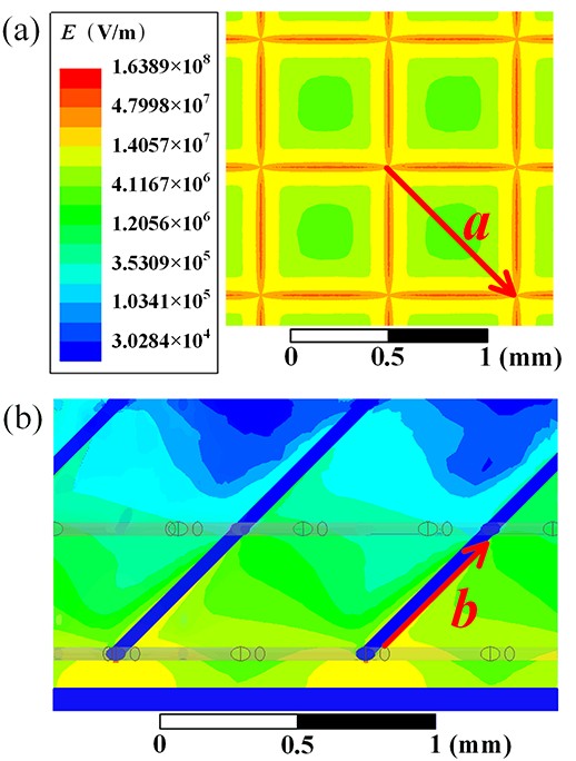
Figure 9 shows the electric field distribution characteristics of the multilayer three-dimensional mesh contact electrode structure. It can be seen that there are two strong electric field regions in the electrode structure. Firstly, compared with the single-layer two-dimensional mesh contact electrode structure, with the same mesh size, because of the presence of the upper electrode, the electric field strength inside the mesh of the insulating layer surface of the multilayer three-dimensional mesh contact electrode structure increases as a whole, and the lowest electric field strength in the center of the mesh also reaches 3.29×10⁶ V/m, which is conducive to the generation of a large-area discharge on the insulating layer surface. Secondly, and more importantly, as can be seen from figure 9(b), the electrode structure forms a region of strong electric field around the vertical wire electrode. Meanwhile, a certain range of strong electric field region is also formed in the space between the vertical wire electrode and the insulating layer. The electrode structure allows the strong electric field region to develop into the space, increasing the area of the strong electric field region in the space, and providing conditions for space-diffuse discharge within the mesh.
Furthermore, it can be expected that by randomly arranging the internal meshes of the multilayer three-dimensional mesh contact electrode structure, the airflow will flow randomly inside the material, which can lead to a better contact between the airflow and the plasma generated by the discharge, and the randomly arranged mesh also helps to extend the airflow passage time and increase the contact time between the plasma and the air pollutants.
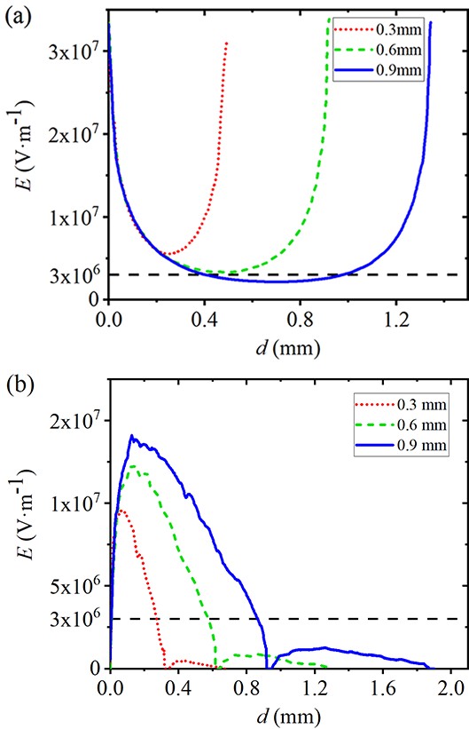
The effects of different mesh sizes on the electric field distribution are compared. The mesh sizes of 0.3 mm, 0.6 mm and 0.9 mm are selected for the electric field simulation. The selected observation line segments are labelled in figure 9, where line segment a is the diagonal of the mesh on the surface of the insulating layer, and line segment b is located on the surface of the vertical wire. The electric field distribution curves obtained are shown in figure 10.
From figure 10(a), it can be seen that the electric field strength inside the mesh on the surface of the insulating layer decreases as the mesh aperture increases. When the mesh size reaches 0.9 mm, the field strengths inside the mesh can no longer all reach 3×10⁶ V/m, which is unfavorable to the diffusion of the insulation surface discharge. However, it can be seen from figure 10(b) that the electric field strength on the surface of the vertical wire increases gradually with the increase of the mesh size. The area of the strong electric field on the surface of the vertical wire also increases with the increase of the mesh size, which is favorable for the generation of the discharge in three-dimensional space. Therefore, the mesh size of about 0.6 mm is selected to achieve a large area and a certain intensity of discharge.
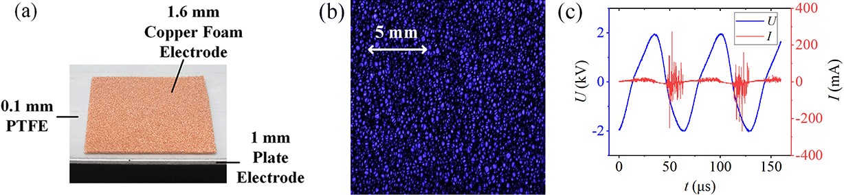
The copper foam contact electrode structure constructed using copper foam material is shown in figure 11(a). The thickness of the copper foam is 1.6 mm, the insulating layer is made of PTFE with a thickness of 0.1 mm, and the lowermost layer is a plate electrode with a thickness of 1 mm. Figure 11(b) shows a top view of the discharge phenomenon of this electrode structure in atmospheric pressure air at an AC voltage of 2 kV. It can be seen that a diffuse blue discharge phenomenon is formed inside the copper foam meshes. As can be seen from the voltage-current waveforms, most of the discharge current pulses are around 100 mA.
In conclusion, the contact electrode structure made of copper foam material can form a three-dimensional non-uniform spatial electric field in the three-dimensional mesh of copper foam without the opposite electrode, thus forming a diffusion discharge in an open space.
In this section, a multilayer wire-copper foam stacked electrode structure is further designed, which has high air permeability and allows air to enter vertically into the interior of the copper foam to make full contact with the plasma generated by the discharge. Air purification experiments are conducted accordingly.
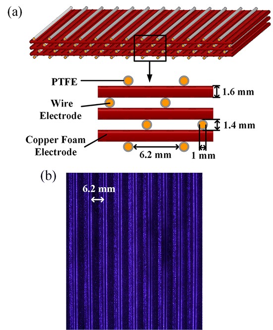
The multilayer wire-copper foam stacked electrode structure is shown in figure 12(a). The discharge electrodes consist of alternating layers of wire electrodes with external insulating tubes and copper foam electrodes. The wire electrode is 1 mm in diameter and 100 mm long, and the insulating tube is made of PTFE sleeve with an inner diameter of 1 mm and an outer diameter of 1.4 mm, which is placed on the outside of the wire electrode. The size of the copper foam is 100 mm×100 mm×1.6 mm. The entire discharge module is a staggered multilayer structure with a multi-electrode array, and the distance between two adjacent insulated wire electrodes in the horizontal direction is about 6.2 mm. The discharge at 1.8 kV and frequency 20 kHz is shown in figure 12(b). It can be seen that a large-area and well-diffused discharge is formed on the surface of the insulating tubes as well as in the meshes of the copper foam. A 2 mm wide diffuse discharge area is formed near the contact surface between each insulated wire electrode and copper foam.
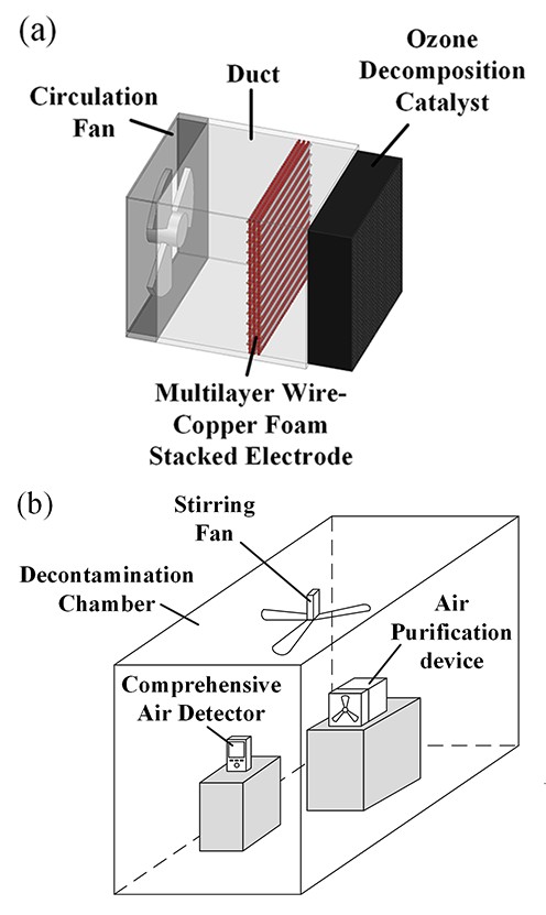
Copper foam extends the passage time of the airflow within it, favoring increased time for the plasma within the copper foam mesh to interact with air pollutants. Therefore, this electrode structure was used to design the air purification device, and a schematic diagram of the device is shown in figure 13(a). Among them, there are four rows of discharge electrodes, and each row contains 13 wire electrodes. Duct cross-section size is 100 mm×100 mm. The ozone decomposition catalyst is a modified porous activated carbon carrying manganese-based composite metal oxides. With the catalyst, the discharge module produced about 0.729 mg/m3 of ozone in 10 min at 1.8 kV.
Air purification experiments were conducted in a 1 m3 experimental chamber with the experimental platform shown in figure 13(b). Air pollutant concentrations were monitored using a model Sensology MEF-500 integrated air detector. Formaldehyde (CH2O) is measured with an accuracy of 0.001 mg/m3 and a maximum range of 2.5 mg/m3, while total volatile organic compounds (TVOC) are measured with an accuracy of 0.001 mg/m3 and a maximum range of 9.999 mg/m3. To simulate actual indoor air pollution, lighting cigarettes were used in this experiment to simultaneously produce pollutants such as formaldehyde and TVOC. A cigarette was lit for each experiment in the experimental chamber, and the stirring fan was switched on to mix the pollutants well with the air. After the cigarettes were fully burnt, the stirring was continued for 10 min and then the stirring fan was switched off. After standing the gas mixture for 10 min, it was used as the time starting point for determining the pollutant concentration t = 0 min, and the initial concentration c0 was recorded. Then, the air purification device was switched on to start the experiment, and the wind speed of the air purification device was set to 1 m/s. During the experiment, data were recorded every 1 min.
The change in pollutant concentration with time was recorded and the decay constant of the pollutant can be calculated according to formula (1). The calculation formula is as follows
| ct=c0e−kt, | (1) |
where ct is the pollutant concentration at time t; c0 is the initial concentration at t = 0; k is the decay constant; and t is time.
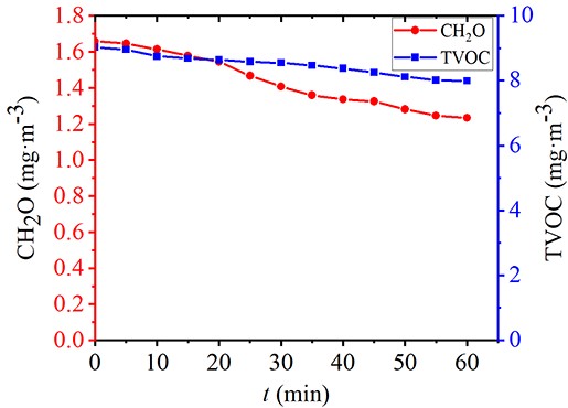
Firstly, the natural attenuation process of formaldehyde and TVOC in the experimental cabin was measured. Figure 14 shows the natural attenuation curve of pollutants. In 60 min, the formaldehyde concentration decayed from 1.658 mg/m3 to 1.233 mg/m3, with a total decay of only about 25.6% and a natural decay constant of 0.00507. The TVOC concentration decayed from 9.032 mg/m3 to 7.996 mg/m3, with a total decay of only about 11.5% and a natural decay constant of 0.00205.
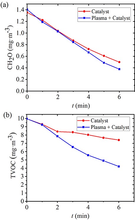
Figure 15(a) shows the formaldehyde treatment effect of the air purification device. In the case of using catalyst only, the formaldehyde concentration decayed from 1.353 mg/m3 to 0.499 mg/m3 in 6 min, with a total decay of about 63.1% and a decay constant of 0.15416; in the case of using discharge plasma combined with a catalyst, the formaldehyde concentration decayed from 1.404 mg/m3 to 0.377 mg/m3, with a total decay of about 73.1% and a decay constant of 0.19126. Figure 15(b) shows the TVOC treatment effect of the air purification device. In the case of using catalyst only, the TVOC concentration decayed from 9.959 mg/m3 to 7.399 mg/m3 in 6 min, with a total decay of about 25.7% and a decay constant of 0.0545; in the case of using discharge plasma combined with a catalyst, the TVOC concentration decayed from 9.959 mg/m3 to 4.204 mg/m3, with a total decay of about 57.8% and a decay constant of 0.13851. The air pollutants such as formaldehyde and TVOC were generated simultaneously during the experiment and the concentration of TVOC was high, so the air purification device treated multiple pollutants at the same time when the air passed through the it. There was a competition between the pollutants for the active particles of the plasma, which might be the reason for the weak treatment effect of plasma on formaldehyde in this experiment.
It can be seen that the air purification device has a strong air purification capability. Moreover, the purifier has a low discharge voltage, a low overall device cost, and a small discharge module size, which is conducive to large-scale applications.
Moreover, in air purification experiments, we find that increasing the discharge voltage and frequency to a certain extent can improve the air purification effect of plasma. However, this will result in higher ozone production, and more ozone treatment catalysts will be required. Therefore, further optimization is required in the future.
In this study, based on the three-dimensional spatial non-uniform electric field, a cooper foam contact electrode structure is proposed to realize the three-dimensional diffusion discharge in atmospheric pressure air. Meanwhile, the discharge characteristics and indoor air purification effect of this electrode structure are investigated through simulation, experiment and testing. The specific conclusions are as follows.
(1) The diffuse discharge can be formed under atmospheric pressure air using a contact electrode structure by using the pre-ionization of the non-uniform electric field and its effect of reducing the collisional ionization coefficient along the development path of the electron avalanche. Meanwhile, by adding a vertically oriented electrode to the contact electrode structure, a three-dimensional non-uniform spatial electric field can be formed, which is conducive to increasing the discharge area. Diffuse discharge can be formed on the surface of the insulating layer and in the open space above it at a voltage of 2 kV.
(2) The contact electrode constructed with copper foam material uses the three-dimensional mesh inside the copper foam to form a three-dimensional non-uniform spatial electric field, which is conducive to the suppression of filamentary discharge and creates conditions for spatially diffuse discharge. Large area diffuse discharge forms in the three-dimensional mesh of the copper foam at a voltage of 2 kV.
(3) The multilayer wire-copper foam stacked electrode structure designed with copper foam material has high air permeability. The air purification device made of it has the characteristics of high purification efficiency, effective removal of various pollutants, lower cost, small size and low discharge voltage.
This work was supported by the Fundamental Research Funds for the Central Universities (No. 2022YJS094).
| [1] |
Asilevi P J et al 2021 Sci. Rep. 11 22830 doi: 10.1038/s41598-021-02276-1
|
| [2] |
Yuan J F et al Experimental study on the removal of formaldehyde by plasma-catalyst In: Proceedings of 2019 4th International Conference on Environmental Engineering and Sustainable Development (CEESD 2019) Xiamen: IOP Publishing 2019, doi: 10.1088/1755-1315/435/1/012004
|
| [3] |
Jung J S and Kim J G 2017 J. Electrostat. 86 12 doi: 10.1016/j.elstat.2016.12.011
|
| [4] |
Stepczyńska M 2016 Plasma Process. Polym. 13 1080 doi: 10.1002/ppap.201600051
|
| [5] |
Roth J R 2005 Phys. Plasmas 12 057103 doi: 10.1063/1.1882293
|
| [6] |
Roth J R, Nourgostar S and Bonds T A 2007 IEEE Trans. Plasma Sci. 35 233 doi: 10.1109/TPS.2007.892711
|
| [7] |
Fang Z et al 2007 J. Phys. D: Appl. Phys. 40 1401 doi: 10.1088/0022-3727/40/5/013
|
| [8] |
Golubovskii Y B et al 2004 J. Phys. D: Appl. Phys. 37 008 doi: 10.1088/0022-3727/37/9/008
|
| [9] |
Zhang S et al 2014 Spectrochim. Acta Part A: Mol. Biomol. Spectrosc. 117 535 doi: 10.1016/j.saa.2013.08.051
|
| [10] |
Yang D Z et al 2012 Plasma Sources Sci. Technol. 21 035004 doi: 10.1088/0963-0252/21/3/035004
|
| [11] |
Jiang H et al 2011 IEEE Trans. Plasma Sci. 39 2076 doi: 10.1109/TPS.2011.2146280
|
| [12] |
Wang Q et al 2018 Plasma Sci. Technol. 20 035404 doi: 10.1088/2058-6272/aaa357
|
| [13] |
Massines F et al 1998 J. Appl. Phys. 83 2950 doi: 10.1063/1.367051
|
| [14] |
Wang X X, Lu M Z and Pu Y K 2002 Acta Phys. Sin. 51 2778 (in Chinese) doi: 10.7498/aps.51.2778
|
| [15] |
Massines F and Gouda G 1998 J. Phys. D: Appl. Phys. 31 3411 doi: 10.1088/0022-3727/31/24/003
|
| [16] |
Buchta J, Brablec A and Trunec D 2000 Czech. J. Phys. 50 273 doi: 10.1007/BF03165893
|
| [17] |
Wang X X et al 2006 Plasma Sources Sci. Technol. 15 845 doi: 10.1088/0963-0252/15/4/030
|
| [18] |
Liu W Z et al 2014 Phys. Plasmas 21 043514 doi: 10.1063/1.4874301
|
| [19] |
Liu W Z, Lei X and Zhao Q 2016 Plasma Sci. Technol. 18 35 doi: 10.1088/1009-0630/18/1/07
|
| [20] |
Liu W Z et al 2018 Plasma Sci. Technol. 20 035401 doi: 10.1088/2058-6272/aa9885
|
| [21] |
Liu W Z et al 2017 Phys. Plasmas 24 093519 doi: 10.1063/1.5004696
|
| [22] |
Zhao L X et al 2018 Phys. Plasmas 25 053515 doi: 10.1063/1.5024454
|
| [1] | Wenzheng LIU (刘文正), Maolin CHAI (柴茂林), Wenlong HU (胡文龙), Luxiang ZHAO (赵潞翔), Jia TIAN (田甲). Generation of atmospheric pressure diffuse dielectric barrier discharge based on multiple potentials in air[J]. Plasma Science and Technology, 2019, 21(7): 74004-074004. DOI: 10.1088/2058-6272/aafdf8 |
| [2] | Wenzheng LIU (刘文正), Chuanlong MA (马传龙), Shuai ZHAO (赵帅), Xiaozhong CHEN (陈晓中), Tahan WANG (王踏寒), Luxiang ZHAO (赵潞翔), Zhiyi LI (李治一), Jiangqi NIU (牛江奇), Liying ZHU (祝莉莹), Maolin CHAI (柴茂林). Exploration to generate atmospheric pressure glow discharge plasma in air[J]. Plasma Science and Technology, 2018, 20(3): 35401-035401. DOI: 10.1088/2058-6272/aa9885 |
| [3] | Wenzheng LIU (刘文正), Tahan WANG (王踏寒), Xiaozhong CHEN (陈晓中), Chuanlong MA (马传龙). Characteristics and application of diffuse discharge of water electrode in air[J]. Plasma Science and Technology, 2018, 20(1): 14003-014003. DOI: 10.1088/2058-6272/aa8fc5 |
| [4] | Yunfeng HAN (韩云峰), Shaoyang WEN (温少扬), Hongwei TANG (汤红卫), Xianhu WANG (王贤湖), Chongshan ZHONG (仲崇山). Influences of frequency on nitrogen fixation of dielectric barrier discharge in air[J]. Plasma Science and Technology, 2018, 20(1): 14001-014001. DOI: 10.1088/2058-6272/aa947a |
| [5] | Hao YUAN (袁皓), Wenchun WANG (王文春), Dezheng YANG (杨德正), Zilu ZHAO (赵紫璐), Li ZHANG (张丽), Sen WANG (王森). Atmospheric air dielectric barrier discharge excited by nanosecond pulse and AC used for improving the hydrophilicity of aramid fibers[J]. Plasma Science and Technology, 2017, 19(12): 125401. DOI: 10.1088/2058-6272/aa8766 |
| [6] | QI Haicheng (齐海成), GAO Wei (高巍), FAN Zhihui (樊智慧), LIU Yidi (刘一荻), REN Chunsheng (任春生). Volume Diffuse Dielectric Barrier Discharge Plasma Produced by Nanosecond High Voltage Pulse in Airflow[J]. Plasma Science and Technology, 2016, 18(5): 520-524. DOI: 10.1088/1009-0630/18/5/13 |
| [7] | LIU Xinghua(刘兴华), XIAN Richang(咸日常), SUN Xuefeng(孙学峰), WANG Tao(王涛), LV Xuebin(吕学宾), CHEN Suhong(陈素红), YANG Fan(杨帆). Space Charge Transient Kinetic Characteristics in DC Air Corona Discharge at Atmospheric Pressure[J]. Plasma Science and Technology, 2014, 16(8): 749-757. DOI: 10.1088/1009-0630/16/8/05 |
| [8] | CHEN Huixia(陈慧黠), XIU Zhilong(修志龙), BAI Fengwu(白凤武). Improved Ethanol Production from Xylose by Candida shehatae Induced by Dielectric Barrier Discharge Air Plasma[J]. Plasma Science and Technology, 2014, 16(6): 602-607. DOI: 10.1088/1009-0630/16/6/12 |
| [9] | TAO Xiaoping (陶小平), LI Meng (李蒙), LI Hui (李辉), DONG Hai (董海). Experimental Study of ZnO-Coated Alumina DBD in Atmospheric Pressure Air[J]. Plasma Science and Technology, 2013, 15(8): 787-790. DOI: 10.1088/1009-0630/15/8/13 |
| [10] | TAO Xiaoping (陶小平), LU Rongde (卢荣德), LI Hui (李辉). Electrical characteristics of dielectric-barrier discharges in atmospheric pressure air using a power-frequency voltage source[J]. Plasma Science and Technology, 2012, 14(8): 723-727. DOI: 10.1088/1009-0630/14/8/08 |
Figures(15)
Supported by: Beijing Renhe Information Technology Co., Ltd. 
 DownLoad: