Figure
1.
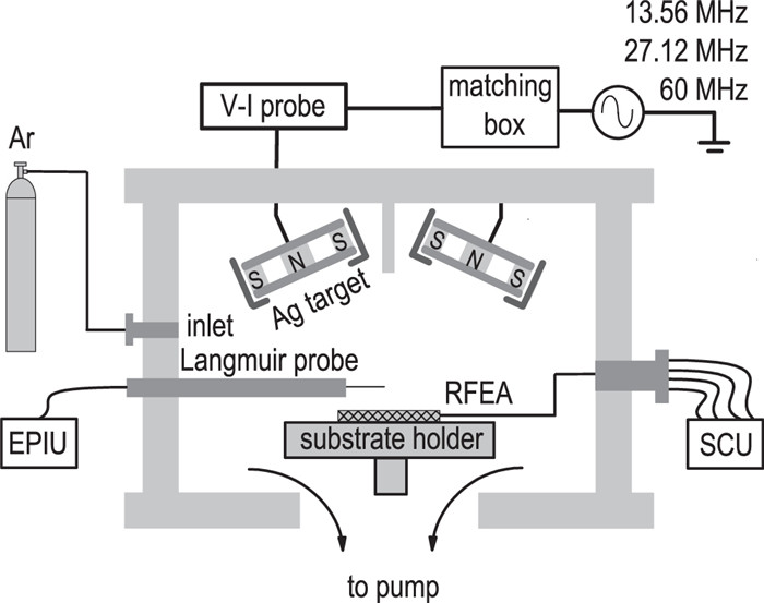
Schematic of the magnetron sputtering discharge setup.
| Citation: |
Weichen NI, Chao YE, Yiqing YU, Xiangying WANG. Effect of gas pressure on ion energy at substrate side of Ag target radio-frequency and very-high-frequency magnetron sputtering discharge[J]. Plasma Science and Technology, 2022, 24(2): 025506. DOI: 10.1088/2058-6272/ac3c3e

|
The effect of gas pressure on ion energy distribution at the substrate side of Ag target radio-frequency (RF) and very-high-frequency (VHF) magnetron sputtering discharge was investigated. At lower pressure, the evolution of maximum ion energy (E) with discharge voltage (V) varied with the excitation frequency, due to the joint contribution of the ion generation in the bulk plasma and the ion movement across the sheath related to the ion transit sheath time τi and RF period τRF. At higher pressure, the evolution of E–V relationships did not vary with the excitation frequency, due to the balance between the energy lost through collisions and the energy gained by acceleration in the electric field. Therefore, for RF and VHF magnetron discharge, lower gas pressure can have a clear influence on the E–V relationship.
Magnetron sputtering is an important tool for the deposition of thin films. Progress made on the magnetron sputtering system in the last several decades has led to its widespread use. During deposition of film using magnetron sputtering, the energy of an ion incident on a substrate surface has a strong influence on the growth and properties of the film, such as the microstructure, crystallography, phase composition, and mechanical and optical properties. Therefore, to understand the mechanism of film growth, the ion energy at the substrate surface is of great interest [1–14].
According to the model of the ion energy distribution at the substrate surface in radio-frequency (RF) magnetron sputtering developed by Garofano et al [1], the energy of an ion incident on the substrate surface was related to the ejection of atoms from the target, their transport in the gas phase, and their acceleration in the sheath near the surface of the substrate [1]. However, for magnetron sputtering, near the target surface, there existed an electric field pointing toward the target, which resulted from the self-bias voltage [2, 14]. The action of this electric field on the sputtered ions led to the positive ions returning to the target and the negative ions going into the bulk plasma [2, 14]. As a result, for metal target magnetron sputtering, the sputtered positive ions could not go into the bulk plasma and had no contribution to the ion energy at the substrate side. The ion energy measured at the substrate side was mainly related to the ionization process (Penning ionization of sputtered atoms, electron impact ionization and charge-exchange collisions) in the bulk plasma, the thermalization process of the sputtered atoms through collisions with the gas atoms, and the movement of ions passing through the sheath.
The ionization and thermalization processes in the bulk plasma are closely related to the operating conditions, such as the working pressure, discharge power, excitation frequency and electrode spacing [1]. The effect of the working pressure, discharge power and electrode spacing on the ion energy has been paid more attention [1, 6, 9, 10], but the effect of excitation frequency, especially at different working pressures, has seldom been reported.
The movement of ions passing through the sheath mainly depends on the excitation frequency, but is also related to the working pressure. If the ion transit sheath time τi is comparable with the RF period τRF of excitation frequency, namely τi < τRF or τi~τRF, the ions can pass through the sheath in one RF period or less [13, 15]. The ion energy at the substrate side mainly depends on the initial energy of the ions and the time at which they enter the sheath [1, 16]. If τi > τRF, the ions cannot pass through the sheath quickly [13, 15]. The ion energy at the substrate side mainly depends on the constant averaged potential acting upon the ions [1, 16]. In addition, in the case of higher pressure, the charge-exchange collisions can also have some influence on the ion movement in the sheath. Therefore, the effect of excitation frequency at different pressures on the ion energy also needs to be considered.
Many investigations on the ion energy at the substrate side have been carried out, but these works focused on the common 13.56 MHz RF magnetron sputtering discharge. For high-frequency magnetron sputtering [17–21], however, the effect of working pressure on the ion energy at the substrate side is lacking. Therefore, in this work, the ion energy at the substrate side of Ag target magnetron sputtering driven by 13.56 MHz, 27.12 MHz and 60 MHz in the pressure range of 1.0–10.0 Pa was investigated.
The experiment was carried out using a homemade magnetron sputtering system, as shown in figure 1. The cylindrical vacuum chamber (350 mm in diameter and 300 mm in height) was used as the main chamber, in which a water-cooled circular Ag target (99.99% pure, 50 mm in diameter) was placed at the top, and the electrically floated stainless steel substrate holder (100 mm in diameter) was set at the bottom, about 70 mm away from the center of the target surface. The Ag target was biased with 13.56 MHz, 27.12 MHz and 60 MHz power through the corresponding matching box. The wall of the chamber was electrically grounded. The discharge voltage and sputtering power for the fundamental frequencies of 13.56 MHz, 27.12 MHz and 60 MHz were measured using an Impedans Octiv Suite V–I probe [22, 23], which was connected between the matching box and the Ag target. The base pressure of the magnetron sputtering system was less than 5 × 10⁻⁴ Pa, evacuated with a 600 l/s turbo-molecular pump backed up with a mechanical pump. Ar was used as the discharge gas and the working pressure was chosen at about 1.0–10.0 Pa with a flow rate of 2.5–17.0 sccm.
The ion velocity distribution function (IVDF) was measured using a Semion HV-2500 retarding field energy analyzer (RFEA), which was placed at the substrate holder. The IVDF is described as follows [24, 25]:
| f(IVDF)=-me2·1TgA0·dIc(φr)dφr | (1) |
where Ic is the detector current, φr is the applied retarding grid potential, m is the mass of ions, Tg is the total geometrical transparency of grids, and A0 is the total ion acceptance area and is equal to 21.5 mm2 for the top face with 37 × 0.83 mm diameter orifices.
The electron temperature Te, electron density ne, plasma potential Vp, and floating potential Vf of the bulk plasma were estimated from the I–V characteristics [12], which were measured at about 20 mm above the center of the substrate surface using a Hiden Analytical RF compensated cylindrical ESPion Langmuir probe.
A horseshoe-type annular magnetic field on the surface of the cathode (Ag target) was distributed by two permanent magnets placed behind the cathode. The intensities of the magnetic field on the cathode surface and at the position of the Langmuir probe, which were measured using a Hall-probe gaussmeter, were about 1182 G and 10 G, respectively. For the application of a cylindrical Langmuir probe in the magnetron sputtering system, in order to avoid the depletion of low-energy electrons by the magnetic field, it was necessary that the radius of the probe (R) should be smaller than the Larmor radius of electrons (rce), i.e. R ≪ rce. Our previous work proved that the condition of R ≪ rce was satisfied and the probe measurement was sufficiently reliable in the downstream region [12].
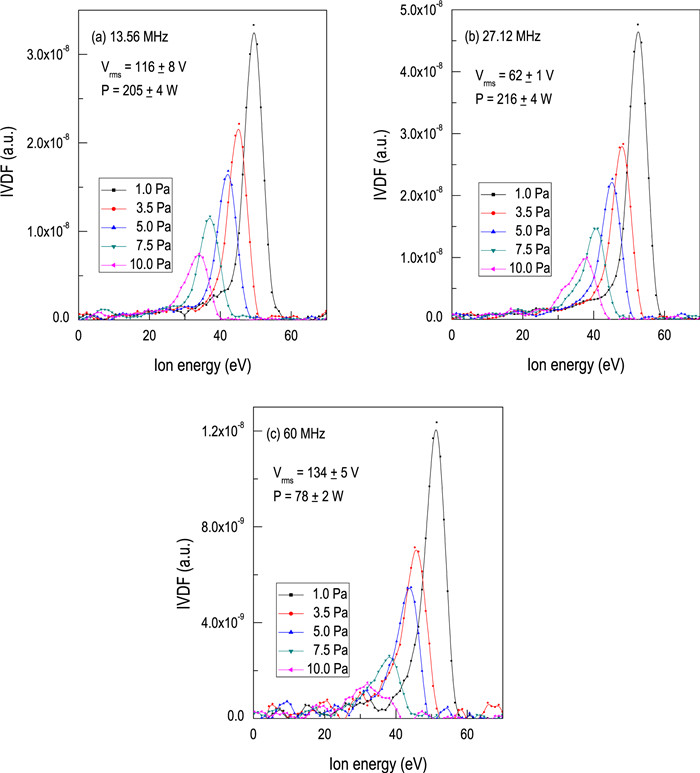
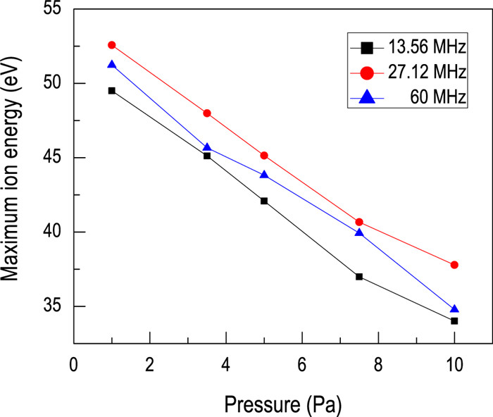
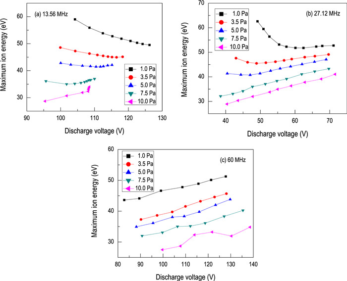
Figure 2 shows the IVDFs at pressure of 1.0–10.0 Pa for 13.56 MHz, 27.12 MHz and 60 MHz driven magnetron sputtering discharge at a discharge voltage (sputtering power) of Vrms=116 ± 8 V (P=205 ± 4 W), Vrms=62 ± 1 V (P=216 ± 4 W) and Vrms=134 ± 5 V (P=78 ± 2 W), respectively. At the pressure of 1.0 Pa, the higher ion energy is found in a single peak at around 49.5 eV, 52.5 eV and 51.2 eV, respectively. However, for the 60 MHz magnetron sputtering, some small low-energy peaks can be obviously seen due to the charge-exchange collisions in the sheath at higher frequency [1]. Upon increasing the pressure, the single peaks all shift to the lower-energy side, and smaller low-energy peaks are developed. This shift of the peaks to lower energy and the development of a low-energy tail with the pressure increase have usually been observed in RF magnetron sputtering [2, 8, 10, 11], and were thought to be due to the increase in collisions in the sheath. At the pressures of 7.5 Pa and 10.0 Pa, a low energy shoulder or low energy peak can be seen due to the increase in collisions within the sheath. The variation of the maximum ion energy E (designated as the ion energy at maximum peak) with the pressure is shown in figure 3. The maximum ion energy is seen to decrease with the pressure increase for the three excitation frequencies.
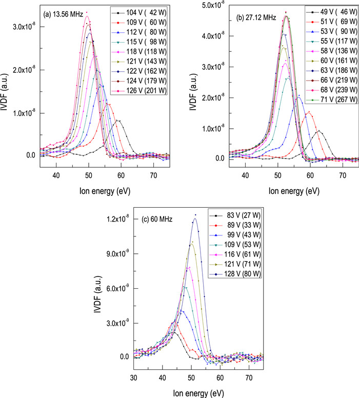
Figure 4 shows the variation of IVDFs with discharge voltage (or sputtering power) at the pressure of 1.0 Pa for the 13.56 MHz, 27.12 MHz and 60 MHz magnetron sputtering cases. The evolution trends are found to be completely different for the different excitation frequencies. For the 13.56 MHz magnetron sputtering, with a discharge voltage increase, the ion energy peak shifts monotonously to the low-energy region. In contrast, for the 60 MHz magnetron sputtering, the single peak shifts monotonously to the high-energy region. However, for the 27.12 MHz magnetron sputtering, the ion energy peak firstly shifts to the low-energy region in the discharge voltage range of 49–60 V and then to the high-energy region in the discharge voltage range of 60–71 V. This evolution of IVDFs with discharge voltage is completely different for the 13.56 MHz and 60 MHz magnetron sputtering operation, and is seldom reported. These results show that at lower pressure the increase in excitation frequency leads to an obvious difference in the evolution of IVDFs with discharge voltage.
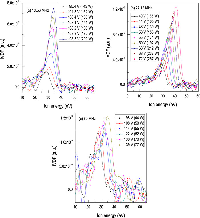
Figure 5 shows the variation of IVDFs with discharge voltage (or sputtering power) at the pressure of 10.0 Pa for the 13.56 MHz, 27.12 MHz and 60 MHz magnetron sputtering. The evolution trends are different from those at 1.0 Pa. With the discharge voltage increase, the ion energy peaks all shift to the high-energy region. In addition, many small energy peaks develop simultaneously in both the low-energy region and the high-energy region, particularly for the 60 MHz magnetron sputtering, due to the increase in charge-exchange collisions at higher pressure and higher frequency. The results show that at higher pressure the excitation frequency has a weak influence on the evolution of IVDFs with discharge voltage.
By plotting the dependence of maximum ion energy (E) on discharge voltage (V), the effect of pressure on the E–V relationship can be clearly seen, as shown in figure 6. It can be found that the pressure has an obvious influence on the E–V relationships for the 13.56 MHz and 27.12 MHz driven magnetron sputtering discharge. For the 13.56 MHz driven magnetron sputtering discharge, the E–V relationship shows a decreasing trend at the pressure of 1.0 Pa. As the pressure increases from 3.5 Pa to 7.5 Pa, the E–V relationships change from the decreasing trend to the initially decreasing and subsequently increasing trend, while at the pressure of 10.0 Pa, the E–V relationship shows an increasing trend. For the 27.12 MHz driven magnetron sputtering discharge, in the pressure range of 1.0–5.0 Pa, the E–V relationships all show an initially decreasing and then increasing trend, but the voltage for this change shifts to the low-voltage region with increasing pressure. In the pressure range of 7.5–10.0 Pa, the E–V relationships all show an increasing trend. For the 60 MHz driven magnetron sputtering discharge, the E–V relationships all show an increasing trend in the pressure range of 1.0–10.0 Pa. Therefore, for different excitation frequencies, the increase in pressure leads to different E–V relationships.
The relationships between the average ion energy and the voltage applied across the electrodes in the capacitive RF plasma discharge and the RF magnetron sputtering discharge have been investigated through the years [1, 26–29]. For the low-pressure RF plasma, the E–V relationship was found to follow a linearly increasing trend [26, 27], and was thought to relate to the energy gained in the sheath due to fewer collisions [26]. However, for the RF magnetron sputtering discharge, the energy of the main peak was found to decrease with increasing bias voltage, which was attributed to a slight decrease in the electron temperature induced by the change in plasma composition as the Ag atoms were sputtered in greater numbers [1]. Therefore, the E–V relationships are different for capacitive RF plasma discharge and RF magnetron sputtering discharge. In this work, however, more complex E–V relationships are obtained, which are found to relate to the working pressure and the driving frequency.
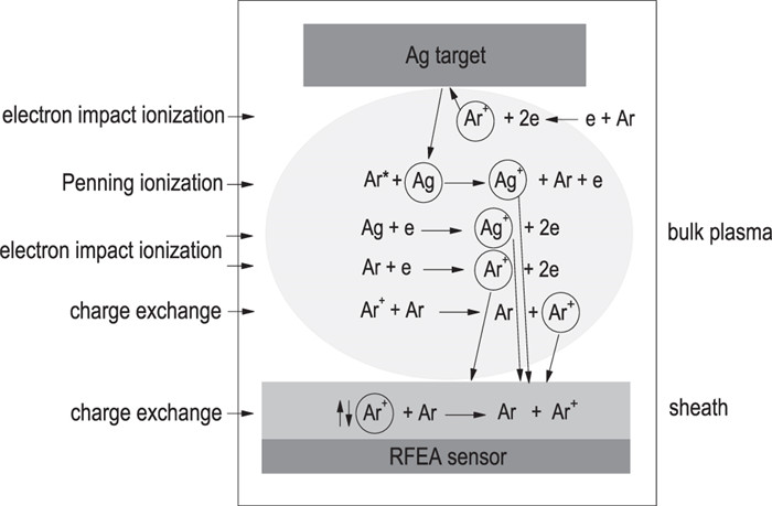
According to Garofano's model and van Hattum's analysis of metal target RF magnetron sputtering, the ion energy at the substrate side is mainly related to the ionization process of sputtered atoms in the bulk plasma, the thermalization process of the ions with background gas atoms, and the movement of ions passing through the sheath. The possible ionization processes taking place in the bulk plasma and in the sheath are plotted as shown in figure 7, and the possible mechanism of the complex E–V relationship is discussed as follows.
For metal target magnetron sputtering, only the sputtered atoms can go into the bulk plasma, and they are mostly ionized in the bulk plasma through Penning ionization and electron impact ionization [1].
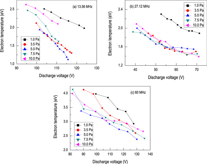
At lower pressure, collisionless plasma can be obtained. The electron impact ionization and the thermalization process in the bulk plasma can be neglected. As the electron density is equal to or lower than 1016 m-3, and the metastable atoms of the working gas are abundant and have relatively high energies, a likely possibility is the Penning ionization process [30–32]. For Ag target magnetron sputtering, the ionization potential (7.58 eV) of Ag [1] is less than the metastable energy (11.55 and 11.72 eV) of Ar* [30]. In addition, at the pressure of 1.0 Pa, the electron density measured using the Langmuir probe is in the range of (0.13–1.48) × 1016 m-3 (for the 13.56 MHz discharge at a discharge voltage of 104–124 V), (0.19–3.14) × 1016 m-3 (for the 27.12 MHz discharge at a discharge voltage of 51–71 V), and (0.15–0.41) × 1016 m-3 (for the 60 MHz discharge at a discharge voltage of 88–128 V), respectively. Therefore, the conditions for the Penning ionization are well satisfied, and the Penning ionization (Ar*+Ag→Ag++Ar+e) between the Ar metastable atom (with kinetic energy) and the neutral Ag atom dominates the generation of ions. As a result, the energy of Ag+ depends on the kinetic energy of Ar metastable atoms. However, the Ar metastable atoms are produced by the energetic electrons impacting near the target surface. Because the electrons gain the energy in the electric field by the E×B rotation, the increase in discharge voltage should increase the electron energy [33]. However, the electron density is found to increase with increasing discharge voltage. This leads to the enhancement of electron–electron collisions and a decrease in electron temperature [12], as shown in figure 8. Therefore, at lower pressure, the increase in discharge voltage should lead to a decrease in ion energy in the bulk plasma.
With a pressure increase, the collision effect increases gradually. The electron impact ionization becomes an important way to produce the ions in the bulk plasma. Therefore, the ion energy is related to the electron temperature. Figure 8 shows the variation of electron temperature with discharge voltage for the 13.56 MHz, 27.12 MHz and 60 MHz magnetron sputtering discharges. It can be seen that with the increase in discharge voltage, the electron temperature almost shows a decreasing trend due to the enhancement of electron–electron collisions. The decrease in electron temperature leads to a decrease in ion energy by electron impact ionization. Therefore, at higher pressure, the increase in discharge voltage leads to a decrease in ion energy in the bulk plasma. In addition, the thermalization process of the ions with the background gas atoms and the charge-exchange collisions also lead to a decrease in ion energy in the bulk plasma.
Because the ion energy measured at the substrate side depends on the energy of ions in the bulk plasma and the energy of ions gained in the sheath, the movement of ions passing through the sheath also has an important influence on the ion energy at the substrate side.
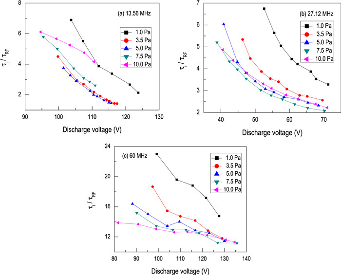
The movement of ions passing through the sheath is related to the ratio of the ion transit sheath time τi to the RF period τRF, dependent on the excitation frequency and working pressure. According to the bulk plasma density n0, electron temperature Te, plasma potential Vp, and floating potential Vf measured using the Langmuir probe, the ion transit time τi is estimated using the following equation [13]:
| τi=3ˉs(Mi2eˉVs)1/2 | (2) |
where the mean sheath width
| ˉs≈23(2ekTe)1/4(ε00.61n0e)1/2ˉV3/4s | (3) |
and the mean sheath potential drop
At lower pressure, the charge-exchange collisions in the sheath are weak. Therefore, the energy of ions gained in the sheath is related to the sheath potential [15, 26], dependent on the ratio of the ion transit sheath time τi to the RF period τRF. From figure 9, it can be seen that the τi/τRF ratios at the pressure of 1.0 Pa are in the range of 6.9–2.1, 6.8–3.3, and 23.0–14.8 for the 13.56 MHz, 27.12 MHz and 60 MHz driven discharges, respectively. The results mean that the cycle of ions passing through the sheath decreases from many RF cycles to several RF cycles for the 13.56 MHz and 27.12 MHz driven discharges. In the case of many RF cycles, the ion responds to the time averaged sheath potential and gains the maximum energy [15]. With the discharge voltage increase, the τi/τRF ratios decrease, and thus the energy of an ion gained in the time averaged sheath potential decreases. In the case of several RF cycles, the ion can traverse the sheath in several RF periods, and gains energy by the instantaneous acceleration of sheath potential. Because the sheath potential increases with discharge voltage, the ion energy gradually increases. As a result, the decrease in ion energy in the bulk plasma is offset by the increase in ion energy in the sheath, leading to a change in the E–V relationship from a decreasing trend to an increasing trend. However, for the 60 MHz driven discharge, the ions must take many more RF cycles to traverse the sheath. Thus, the ion can gain more energy during traversing the sheath. As a result, the energy decrease in the bulk plasma is completely offset by the energy increase in the sheath due to the increase in sheath potential, leading to the monotonous increase of the E–V relationship.
With a pressure increase, the charge-exchange collisions in the sheath increase gradually. When the ions pass through the sheath, they go through a sufficient number of collisions, reaching a balance between energy lost through collisions and energy gained by acceleration in the electric field [26]. Therefore, the ion energy mainly depends on the time averaged sheath potential. At the pressures of 3.5 Pa and 5.0 Pa, the energy decrease in the bulk plasma is partly offset by the energy increase in the sheath due to the increase in sheath potential. Thus, the evolution of the E–V relationship shows a similar trend to that of 1.0 Pa. At the pressures of 7.5 Pa and 10.0 Pa, the energy decrease in the bulk plasma is completely offset by the energy increase in the sheath, leading to an increasing trend in the E–V relationship.
The effect of working pressure on the ion energy distribution at the substrate side of Ag target RF and very-high-frequency (VHF) magnetron sputtering discharge was investigated. At lower pressure, the evolution of maximum ion energy (E) with discharge voltage (V) varied with the excitation frequency, and exhibited a decreasing trend for the 13.56 MHz driven magnetron sputtering discharge, an initially decreasing and then increasing trend for the 27.12 MHz driven magnetron sputtering discharge, and an increasing trend for the 60 MHz driven magnetron sputtering discharge. This evolution is due to the joint contribution of the ion generation in the bulk plasma and the ion movement across the sheath related to the ion transit sheath time τi and the RF period τRF in the collisionless plasma. At higher pressure, the evolutions of the E–V relationships all show an increasing trend for the 13.56 MHz, 27.12 MHz and 60 MHz driven magnetron sputtering discharges, and do not vary with the excitation frequency. This evolution is related to the balance between the energy lost through collisions and the energy gained by acceleration in the electric field. Therefore, for the RF and VHF magnetron discharge, lower gas pressure can have a clear influence on the E–V relationship.
The work was supported by National Natural Science Foundation of China (No. 11275136).
| [1] |
Garofano V et al 2019 J. Vac. Sci. Technol. A 37 021301 doi: 10.1116/1.5054101
|
| [2] |
van Hattum E D et al 2007 Appl. Phys. Lett. 91 171501 doi: 10.1063/1.2801514
|
| [3] |
Krumme J P et al 1991 J. Appl. Phys. 70 6743 doi: 10.1063/1.349848
|
| [4] |
Mráz S and Schneider J M 2006 Appl. Phys. Lett. 89 051502 doi: 10.1063/1.2266888
|
| [5] |
Ishijima T et al 2009 Jpn. J. Appl. Phys. 48 116004 doi: 10.1143/JJAP.48.116004
|
| [6] |
Martin N et al 2001 Surf. Coat. Technol. 138 77 doi: 10.1016/S0257-8972(00)01127-0
|
| [7] |
Richter F et al 2009 Surf. Coat. Technol. 204 845 doi: 10.1016/j.surfcoat.2009.09.034
|
| [8] |
Kadlec S et al 1997 Surf. Coat. Technol. 89 177 doi: 10.1016/S0257-8972(96)03088-5
|
| [9] |
Seeger S 2009 J. Appl. Phys. 105 053305 doi: 10.1063/1.3086618
|
| [10] |
Kusano E et al 1999 Surf. Coat. Technol. 120–121 189 doi: 10.1016/S0257-8972(99)00453-3
|
| [11] |
Pokorný P et al 2017 Vacuum 143 438 doi: 10.1016/j.vacuum.2017.06.032
|
| [12] |
Huang F et al 2014 Plasma Sources Sci. Technol. 23 015003 doi: 10.1088/0963-0252/23/1/015003
|
| [13] |
Ye C et al 2014 Phys. Plasmas 21 043509 doi: 10.1063/1.4873401
|
| [14] |
Palmero A et al 2004 J. Appl. Phys. 95 7611 doi: 10.1063/1.1728295
|
| [15] |
Schweigert I V 2008 Appl. Phys. Lett. 92 261501 doi: 10.1063/1.2955526
|
| [16] |
Chabert P and Braithwaite N 2011 Physics of Radio-Frequency Plasmas (New York: Cambridge University Press)
|
| [17] |
Jang Y H 1997 J. Electrochem. Soc. 144 3973 doi: 10.1149/1.1838121
|
| [18] |
He H et al 2014 ECS J. Solid State Sci. Technol. 3 Q74 doi: 10.1149/2.008405jss
|
| [19] |
Prenzel M et al 2013 J. Phys. D: Appl. Phys. 46 084004 doi: 10.1088/0022-3727/46/8/084004
|
| [20] |
Guo J et al 2017 Plasma Sci. Technol. 19 075502 doi: 10.1088/2058-6272/aa6395
|
| [21] |
Yang P et al 2017 Plasma Sci. Technol. 19 085504 doi: 10.1088/2058-6272/aa6619
|
| [22] |
Gahan D et al 2005 Rev. Sci. Instrum. 76 106107 doi: 10.1063/1.2090287
|
| [23] |
Liu X et al 2020 IEEE Trans. Plasma. Sci. 48 99 doi: 10.1109/TPS.2019.2958317
|
| [24] |
Stranak V et al 2012 Surf. Coat. Technol. 206 2801 doi: 10.1016/j.surfcoat.2011.11.043
|
| [25] |
Stranak V et al 2011 Eur. Phys. J. D 64 427 doi: 10.1140/epjd/e2011-20393-7
|
| [26] |
Liu J, Huppert G L and Sawin H H 1990 J. Appl. Phys. 68 3916 doi: 10.1063/1.346278
|
| [27] |
Wild Ch and Koidl P 1989 Appl. Phys. Lett. 54 505 doi: 10.1063/1.100913
|
| [28] |
Toups M F and Ernie D W 1990 J. Appl. Phys. 68 6125 doi: 10.1063/1.346900
|
| [29] |
Zeuner M, Neumann H and Meichsner J 1997 Jpn. J. Appl. Phys. 36 4711 doi: 10.1143/JJAP.36.4711
|
| [30] |
Gudmundsson J T 2020 Plasma Sources Sci. Technol. 29 113001 doi: 10.1088/1361-6595/abb7bd
|
| [31] |
Coburn J W and Kay E 1971 Appl. Phys. Lett. 18 435 doi: 10.1063/1.1653483
|
| [32] |
Ball D J 1972 J. Appl. Phys. 43 3047 doi: 10.1063/1.1661657
|
| [33] |
Borah S M et al 2011 Chin. Phys. B 20 014701 doi: 10.1088/1674-1056/20/1/014701
|
| [34] |
Gahan D et al 2012 Plasma Sources Sci. Technol. 21 015002 doi: 10.1088/0963-0252/21/1/015002
|
| [35] |
Kawamura E et al 1999 Plasma Sources Sci. Technol. 8 R45 doi: 10.1088/0963-0252/8/3/202
|
| [36] |
Bradley J W et al 2002 Plasma Sources Sci. Technol. 11 165 doi: 10.1088/0963-0252/11/2/307
|
| [1] | Min ZHU (朱敏), Chao YE (叶超), Xiangying WANG (王响英), Amin JIANG (蒋阿敏), Su ZHANG (张苏). Effect of radio-frequency substrate bias on ion properties and sputtering behavior of 2 MHz magnetron sputtering[J]. Plasma Science and Technology, 2019, 21(1): 15507-015507. DOI: 10.1088/2058-6272/aae7dd |
| [2] | Amin JIANG (蒋阿敏), Chao YE (叶超), Xiangying WANG (王响英), Min ZHU (朱敏), Su ZHANG (张苏). Ion property and electrical characteristics of 60 MHz very-high-frequency magnetron discharge at low pressure[J]. Plasma Science and Technology, 2018, 20(10): 105401. DOI: 10.1088/2058-6272/aad379 |
| [3] | Yan YUAN (袁燕), Lizhen YANG (杨丽珍), Zhongwei LIU (刘忠伟), Qiang CHEN (陈强). High power impulse magnetron sputtering and its applications[J]. Plasma Science and Technology, 2018, 20(6): 65501-065501. DOI: 10.1088/2058-6272/aa9e48 |
| [4] | Yue HUA (滑跃), Jian SONG (宋健), Zeyu HAO (郝泽宇), Gailing ZHANG (张改玲), Chunsheng REN (任春生). Effects of direct current discharge on the spatial distribution of cylindrical inductivelycoupled plasma at different gas pressures[J]. Plasma Science and Technology, 2018, 20(1): 14005-014005. DOI: 10.1088/2058-6272/aa8ea8 |
| [5] | Peifang YANG (杨培芳), Chao YE (叶超), Xiangying WANG (王响英), Jiamin GUO (郭佳敏), Su ZHANG (张苏). Control of growth and structure of Ag films by the driving frequency of magnetron sputtering[J]. Plasma Science and Technology, 2017, 19(8): 85504-085504. DOI: 10.1088/2058-6272/aa6619 |
| [6] | Jiamin GUO (郭佳敏), Chao YE (叶超), Xiangying WANG (王响英), Peifang YANG (杨培芳), Su ZHANG (张苏). Growth and structural properties of silicon on Ag films prepared by 40.68 MHz veryhigh-frequency magnetron sputtering[J]. Plasma Science and Technology, 2017, 19(7): 75502-075502. DOI: 10.1088/2058-6272/aa6395 |
| [7] | Liang SONG (宋亮), Xianping WANG (王先平), Le WANG (王乐), Ying ZHANG (张营), Wang LIU (刘旺), Weibing JIANG (蒋卫斌), Tao ZHANG (张涛), Qianfeng FANG (方前锋), Changsong LIU (刘长松). Fabrication and characterization of He-charged ODS-FeCrNi films deposited by a radio-frequency plasma magnetron sputtering technique[J]. Plasma Science and Technology, 2017, 19(4): 45502-045502. DOI: 10.1088/2058-6272/aa57f0 |
| [8] | MIAO Chunguang (苗春光), WANG Xiangqin (王相勤). Mass Deposition, Etching and Sputtering Effects of Low-Energy N + Ion Irradiation on Solid Fly Ash[J]. Plasma Science and Technology, 2013, 15(12): 1232-1236. DOI: 10.1088/1009-0630/15/12/13 |
| [9] | WANG Qing (王庆), WANG Yongfu (王永富), BA Dechun (巴德纯), YUE Xiangji (岳向吉). The Effect of Ion Current Density on Target Etching in Radio Frequency-Magnetron Sputtering Process[J]. Plasma Science and Technology, 2012, 14(3): 235-239. DOI: 10.1088/1009-0630/14/3/09 |
| [10] | MU Zongxin, LIU Shengguang, ZANG Hairong, WANG Chun, MU Xiaodong. Discharge Properties of High-Power Pulsed Unbalanced Magnetron Sputtering[J]. Plasma Science and Technology, 2011, 13(6): 667-671. |
| 1. | Fu, Y., Ji, P., He, M. et al. Study of Plasma Particle Distribution and Electron Temperature in Cylindrical Magnetron Sputtering. Plasma Chemistry and Plasma Processing, 2023. DOI:10.1007/s11090-023-10425-9 |
| 2. | Fu, Y., Peng, J., He, M. et al. DC Magnetron Sputtering Particle Distribution and Energy Simulation Study. 2023. DOI:10.1109/ICEMPE57831.2023.10139580 |
Supported by: Beijing Renhe Information Technology Co., Ltd. 
 DownLoad: