Ruirong LIANG, Xianzu GONG, Bin ZHANG, Zhendong YANG, Manni JIA, Youwen SUN, Qun MA, Jiayuan ZHANG, Yunchan HU, Jinping QIAN, the EAST Team. Study on divertor heat flux under n = 3 and n = 4 resonant magnetic perturbations using infrared thermography diagnostic in EAST[J]. Plasma Science and Technology, 2022, 24(10): 105103. DOI: 10.1088/2058-6272/ac73e6
Citation:
Ruirong LIANG, Xianzu GONG, Bin ZHANG, Zhendong YANG, Manni JIA, Youwen SUN, Qun MA, Jiayuan ZHANG, Yunchan HU, Jinping QIAN, the EAST Team. Study on divertor heat flux under n = 3 and n = 4 resonant magnetic perturbations using infrared thermography diagnostic in EAST[J]. Plasma Science and Technology, 2022, 24(10): 105103. DOI: 10.1088/2058-6272/ac73e6
Ruirong LIANG, Xianzu GONG, Bin ZHANG, Zhendong YANG, Manni JIA, Youwen SUN, Qun MA, Jiayuan ZHANG, Yunchan HU, Jinping QIAN, the EAST Team. Study on divertor heat flux under n = 3 and n = 4 resonant magnetic perturbations using infrared thermography diagnostic in EAST[J]. Plasma Science and Technology, 2022, 24(10): 105103. DOI: 10.1088/2058-6272/ac73e6
Citation:
Ruirong LIANG, Xianzu GONG, Bin ZHANG, Zhendong YANG, Manni JIA, Youwen SUN, Qun MA, Jiayuan ZHANG, Yunchan HU, Jinping QIAN, the EAST Team. Study on divertor heat flux under n = 3 and n = 4 resonant magnetic perturbations using infrared thermography diagnostic in EAST[J]. Plasma Science and Technology, 2022, 24(10): 105103. DOI: 10.1088/2058-6272/ac73e6
Resonant magnetic perturbations (RMPs) with high toroidal mode number n are considered for controlling edge-localized modes (ELMs) and divertor heat flux in future ITER H-mode operations. In this paper, characteristics of divertor heat flux under high-n RMPs (n = 3 and 4) in H-mode plasma are investigated using newly upgraded infrared thermography diagnostic in EAST. Additional splitting strike point (SSP) accompanying with ELM suppression is observed under both RMPs with n = 3 and n = 4, the SSP in heat flux profile agrees qualitatively with the modeled magnetic footprint. Although RMPs suppress ELMs, they increase the stationary heat flux during ELM suppression. The dependence of heat flux on q95 during ELM suppression is preliminarily investigated, and further splitting in the original strike point is observed at q95=4 during ELM suppression. In terms of ELM pulses, the presence of RMPs shows little influence on transient heat flux distribution.
Long pulse high-performance H-mode operation is the foreseen scenario for future fusion devices like ITER and CFETR. However, edge localized modes (ELMs) existing in H-mode plasma could lead to periodic bursts of tremendous transient heat flux striking the plasma-facing components, especially the divertor targets. Resonant magnetic perturbation (RMP) is an effective means of controlling ELMs and meanwhile manipulating stationary heat flux (SHF) [1–3]. Many devices have equipped with RMP coils for investigation on ELM and divertor heat flux control via RMPs, such as ASDEX Upgrade [4–8], DIII-D [3, 9–14], EAST [15–20], HL-2A [21, 22], JET [23, 24], KSTAR [25, 26], MAST [27–29], NSTX [30, 31], TEXTOR [32–35]. Theoretical simulation and experiment results have shown that the imposed external RMP field could modify the topology of edge magnetic field and induce the 2D pattern heat flux on divertor target often appearing as strike point splitting [6, 19, 27, 36]. The basic RMP parameters, i.e. RMP coil current (IRMP), toroidal mode number (n), current phase difference between the upper and lower coils (∆φUL), are proved to play a critical role in redistributing the divertor heat flux [6, 23, 26, 30, 37]. In previous work, the RMPs have been demonstrated to control the divertor heat flux. On ASDEX Upgrade, a wider divertor SHF distribution has been observed with rotating RMP under toroidal mode number n = 2 in L-mode plasmas [6]. On DIII-D, a mix of n = 2 rotating RMP and n = 3 static RMP has successfully demonstrated divertor heat flux control during ELM suppression in H-mode discharges [13]. These results shed a light on the development of divertor heat flux control technology. However, most of the previous experiment results are implemented under low-n RMPs. Considering low-n RMPs could easily lead to lock-mode, high-n RMPs (n≥3) are more preferred for ELM and divertor heat flux control in future ITER H-mode operations [1], and divertor heat flux pattern under high-n RMPs in H-mode plasmas still need more investigations.
EAST is a supper-conducting tokamak dedicated to long pulse H-mode operation and has equipped with an RMP system that can generate an RMP spectrum with a high toroidal mode number (n = 3 or 4) and infrared (IR) thermography diagnostic system that allows investigation of the divertor heat flux pattern. In this work, divertor heat flux characteristics under n = 3 and n = 4 RMPs are investigated using newly upgraded IR thermography diagnostic on EAST.
The structure of this paper is as follows. In section 2, the RMP system, IR diagnostic on EAST and heat flux calculation code are introduced. In section 3, experiment results on divertor heat flux under n = 3 and n = 4 RMPs are analyzed. Section 4 gives the summary.
2.
Experiments setup
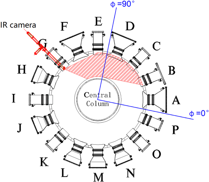
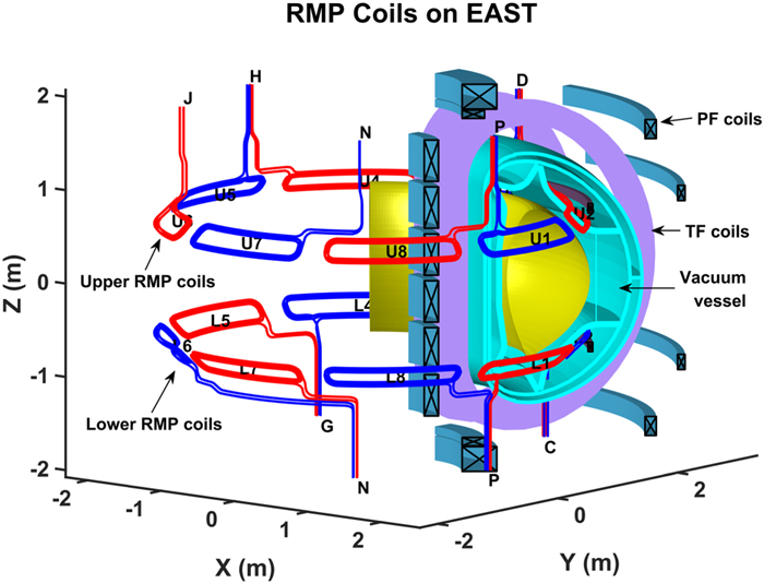
Two arrays of in-vessel RMP coils have been symmetrically installed on the upper and lower parts of EAST device to generate 3D perturbated magnetic fields, as shown in figure 1(a). The upper array coils (named as U1–U8) and lower array coils (named as L1–L8) are evenly distributed along the toroidal direction, with each coil consisting of 4 turns. These sixteen RMP coils are controlled by a flexible power supply system enabling various RMP operation parameters. The maximum amplitude of RMP coil current IRMP can reach up to 3 kA (12 kAt) in DC, or AC mode commonly used to obtain rotating RMPs. The RMP coil arrays can form perturbated magnetic fields with toroidal mode number n from 1 to 4. RMP poloidal spectrum is then controlled by varying the phase difference between upper and lower coils defined as ∆φUL=φU-φL, where φU and φL represent the current phase of upper and lower coils respectively [19]. In the cases of n ranging from 1 to 3, the ∆φUL can be scanned from 0° to 360° or fixed at a specific value. In the case of n = 4, ∆φUL can only be set as 0° or 180° due to the limit number of RMP coils. In this work, static RMPs with n = 3 and n = 4 are applied.
Figure
1.
Layout of RMP coil system on EAST, showing the configuration of RMP with n = 4 and ∆φUL = 180°.
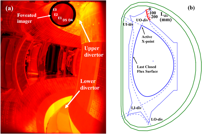
The preferred diagnostic for surface temperature measurement on divertor target is infrared (IR) thermography. A set of IR/Visible integrated endoscope diagnostic systems is installed at the midplane of EAST on port G as shown in figure 2. The system monitors in the clockwise direction and covers the ports from E to B, as indicated by the red shaded area in figure 2. The optic is designed with a large field of view (FOV) of 49.5°×62° and is capable to monitor the upper and lower divertor targets simultaneously, as shown in figure 3(a). The IR camera is a TELOPS TS-IR MW MCT model, with a sampling rate of 115 Hz at a full frame size of 640×512 and up to 4.8 kHz at a reduced frame of 72×40 pixels [38]. The working bandwidth of the IR camera is 3‒4.9 μm with a temperature measurement range of room temperature (RT) to 2500 ℃. Recently, the IR diagnostic system has been upgraded by developing a dynamic foveated imager system which improves the local spatial resolution from 4 mm pixel-1 to 2 mm pixel-1 on divertor targets [39]. In this study, the IR camera was set in a small window of 184×160 pixels with a sampling rate of 1 kHz viewing on the upper-outer (UO) diverter through the foveated imager. As figure 3(a) shows, the location of the dynamic foveated imager was fixed at the view of divertor on ports D and E, covering five ITER-like tungsten divertor cassettes named D4, D5, E1, E2 and E3, and the D5 cassette (at a toroidal angle ϕ=88°) is chosen for the following heat flux analysis. The geometry of the EAST divertor is shown in figure 3(b) with a red plotting scale ranging from 0 to 250 mm. Ldiv in millimeter represents the poloidal distance from one point on the target to divertor corner (Ldiv=0mm).
Figure
2.
Top view of EAST ports from A to P and the installation of the IR camera on port G. The toroidal angle ϕ is defined as positive in the counterclockwise direction, and ϕ=0° is defined as the middle of ports A and P; the IR camera is installed at the midplane of port G and views in the clockwise direction, the field of view is indicated by the red shaded area.
Figure
3.
(a) The field of view of the IR diagnostic system, (b) the plotting scale in red indicates the length (Ldiv) of one point on target to divertor corner; the magnetic surface in blue represents the equilibrium reconstruction in shot #91554 with the upper single null configuration at time slice of 6.38 s during the ELM-free period.
In order to get a reliable surface temperature measurement of divertor target, careful calibration of IR parameters has been carried out using a blackbody furnace with a temperature range of RT to 700 ℃, indicating that the transmittance of the optical path is 0.19 at the central area of foveated imager. The emissivity of the tungsten monoblock surface at the upper divertor is 0.55, which is calibrated during vacuum baking with the help of the thermocouple system on EAST.
Divertor heat flux profile at one fixed toroidal angle is then calculated by a newly self-developed computation code using surface temperature obtained by the IR camera based on the finite element method, which is dedicated to EAST W/Cu monoblock divertor with active water-cooling. The reliability of this code was verified by comparing the calculation results with ANSYS under the same condition [40]. During the plasma shots, the formation of a thin layer on the divertor surface due to depositions not only affects the temperature measurement accuracy of IR system but also reduces the thermal conductivity of divertor target. For evaluating the influence of this thin layer, a heat transmission coefficient (so called alpha factor) is introduced into the heat flux calculation code, with its value determined by a criterion of the energy deposition equilibrium, i.e. the energy deposition on the divertor target should keep constant after the discharge terminated, since no more heat flux from plasma would deposit on divertor. The alpha value of 12 500 W m-2 K-1 satisfies the criterion and is used for the following heat flux calculations.
3.
Divertor heat flux characteristics under RMP
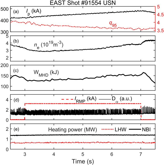
As is known that q95 and RMP ∆φUL are important parameters in satisfying the resonant condition for RMP suppressing ELMs. In experiments, ELM suppression usually occurs at some specific q95 and ∆φUL windows [41]. In order to find the resonant condition for ELM suppression, EAST shots #91553, #91557, #91554 and #91558 were operated with scanned q95 from 4 to 3.5 and varied RMP ∆φUL, with very similar plasma conditions. In these shots, RMPs were set with the same toroidal mode number n = 3 and the same amplitude of coil current IRMP = 3 kA, however, phase differences between upper and lower coils ∆φUL were pre-set as 0°, 90°, 180° and 270°, respectively. Among these shots, ELM suppression was only observed in shot #91554 with RMP ∆φUL = 180° at q95≈3.64. Plasma parameters for these shots were very similar, taking shot #91554 as an example, it was operated in H-mode with upper single null configuration indicated by the equilibrium reconstruction shown in figure 3(b) and with toroidal magnetic field BT = 1.6 T. Other parameters are shown in figure 4: safety factor at 95% normalized poloidal flux q95 scanned from 4 to 3.5 as plasma current Ip ramped up from 420 to 480 kA; line averaged density ne~3–4.3 (1019 m-3); plasma stored energy WMHD~126‒153 kJ; RMP application from 3 to 7 s with n = 3, IRMP = 3 kA, ∆φUL = 180°; plasma heating power of 0.65 MW lower hybrid wave and 1.42 MW neutral beam.
Figure
4.
Time traces of plasma parameters in shot #91554: (a) plasma current (black solid curve) ramping up from 420 to 480 kA meanwhile q95 (red dashed curve) ramping down from 4 to 3.5, (b) line averaged density, (c) plasma stored energy, (d) RMP application from 3 to 7 s with IRMP = 3 kA, n = 3, ∆φUL = 180°; Dα signals indicate the ELM suppression period from 6340 to 6380 ms, (e) heating power of LHW and NBI.
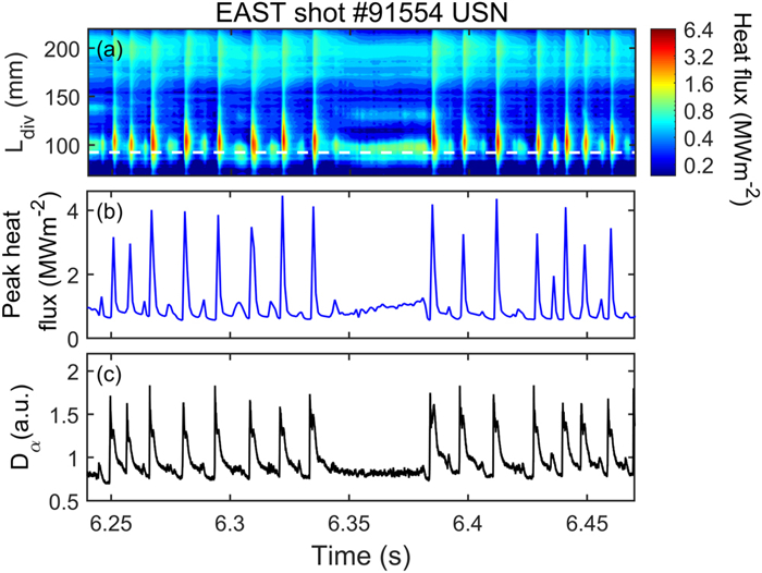
As RMP was switched on, there was a slight descent in plasma density ne and stored energy WMHD due to RMP pump-out effect [2, 42]. However, as plasma evolved, plasma density and stored energy gradually increased and recovered to the level before RMP application. ELMs were mitigated during the whole RMP application, appearing as the increase in ELM frequency and decrease in ELM amplitude, indicated by the Dα signals shown in figure 4(d). In terms of ELM suppression, it was observed when q95 decreased to around 3.64, confirmed by the elimination of pulses in Dα signals from 6340 to 6380 ms. The heat flux during the ELM suppression period is shown in figure 5. During the ELM suppression period, a splitting strike point (SSP) appeared at the position around 120–140 mm on divertor, as seen in figure 5(a). While no SSP was found at the same position at nearby inter-ELM phases (with very close q95 ~ 3.64) before or after ELM suppression.
Figure
5.
Time traces of divertor heat flux and Dα signals for shot #91554, revealing a short ELM-free phase from 6340 to 6380 ms: (a) time evolution of contour of divertor heat flux; the white dashed line indicates the strike point position calculated from EFIT [43], (b) divertor peak heat flux reaches around 4 MW m-2 at ELM pulse and around 1.2 MW m-2 during ELM-free phase, (d) Dα signals indicate ELM pulses and ELM-free period.
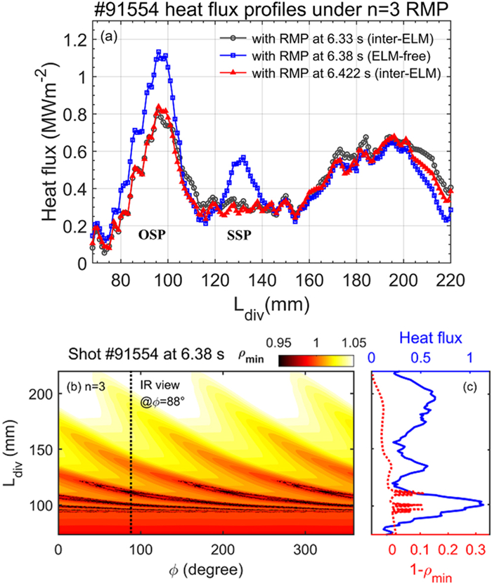
The comparison between heat flux profiles at ELM suppression and nearby inter-ELM phases is shown in figure 6(a). Compared to inter-ELM heat flux, heat flux during ELM suppression increased at the original strike point (OSP) by a factor of 37%. Besides, there appeared an SSP at the position around 120–140 mm, while no SSP was found at the same position in inter-ELM heat flux profiles. During RMP application, the formation of magnetic lobes structure is responsible for the strike point splitting in particle flux and heat flux [6, 19, 23]. To qualitatively understand the splitting heat flux pattern, a magnetic footprint modeling in a vacuum paradigm is implemented by field line tracing code TOP2D [18]. In the modeling, we use ρmin to describe the magnetic footprint. Here, ρmin represents the normalized radius of the minimum flux surface reached by each field line in the radial coordinate of the magnetic surface, and the penetration depth of the magnetic field line is defined as 1-ρmin which represents the distance of minimum flux surface to last closed flux surface (LCFS, ρ=1). So, 1-ρmin>0 represents the case that the field line penetrates deep inside the LCFS to the main plasma, and 1-ρmin<0 represents a shallow penetration in the scrape-off layer. Figure 6(b) shows the spiral magnetic footprint produced by n = 3 RMP on divertor target in shot #91554 at time slice of 6.38 s during the ELM suppression period. The black dashed line indicates the IR view at a toroidal angle ϕ=88° (position of D5 cassette) on divertor. Theoretically, the spiral structure of the magnetic footprint induces a 2D heat flux pattern on divertor target. From the fixed angle view of the IR camera, this manifests as the splitting in strike point. As shown in figure 6(c), the splitting heat flux profile agrees qualitatively with the magnetic footprint presented as field line penetration depth 1-ρmin extracted from a toroidal angle ϕ=88°.
Figure
6.
(a) Comparison of heat flux profiles in shot #91554 revealing the further strike point splitting during ELM suppression, (b) magnetic footprint at time slice 6.38 s in shot #91554 with n = 3 RMP and q95≈3.64, the black dashed line shows the IR view at a toroidal angle ϕ=88° of divertor, (c) a qualitative agreement between the shapes of magnetic footprint (red dashed curve) and splitting heat flux profile (blue solid curve).
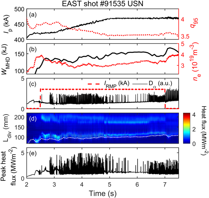
This phenomenon of further splitting in heat flux profile synchronous with ELM suppression was also observed in shot #91535 under n = 4 RMP application. In this shot, RMP was applied from 2.5 to 7.0 s with parameters: n = 4, IRMP = 3 kA and ∆φUL = 180°. It has the same heating power as shot #91554, other plasma parameters are shown in figure 7. The plasma current ramped up from 420 to 470 kA in time duration of 3–5 s (then kept constant at 470 kA until 7.5 s), meanwhile, the q95 ramped down from 3.9 to around 3.5, as shown in figure 7(a). ELMs were suppressed as q95 ramped down to around 3.5 for several time intervals from 4.8 to 6.4 s, indicated by the elimination of the pulses in both Dα signals in figure 7(c) and heat flux in figure 7(e). The plasma density and stored energy increased during ELM suppression periods from 4.8 to 6.4 s and decreased when ELM suppression was lost. As RMP was switched off at 7.0 s, plasma density and stored energy recovered, and at the same time, ELMs became larger indicated by the increase in the amplitude of Dα signals and also the ELM peak heat flux in figure 7(e). As seen in figure 7(d), accompanied by ELM suppression, there existed an obvious additional SSP at the position around 160–180 mm on divertor target. The white dash line indicates the strike point position calculated from EFIT [43]. Note that the time scale in figure 7(d) is too large to show the details of heat flux of the ELM pulses as figure 5 does.
Figure
7.
Evolution of plasma and divertor heat flux during RMP application in shot #91535. (a) Plasma current (black solid curve) ramping up from 420 to 470 kA during the period of 3–5 s and meanwhile q95 (red dashed curve) ramping down from 3.9 to 3.5, (b) plasma stored energy (black solid curve) and line averaged density (red dashed curve), (c) RMP with n = 4, IRMP = 3 kA and ∆φUL = 180° was applied from 2.5 to 7.0 s, Dα signals indicate the periods of ELM suppression, (d) time evolution of contour of divertor heat flux; the white dashed line indicates the strike point position calculated from EFIT [43], (e) divertor peak heat flux.
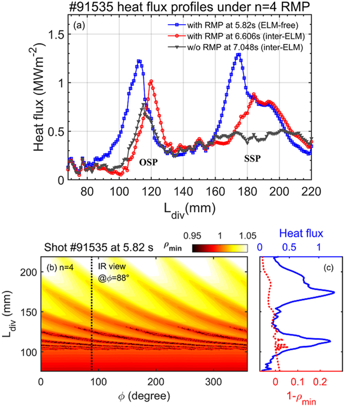
In order to investigate the effect of high-n RMP application and also ELM suppression on heat flux, heat flux profiles at time slices of 5.820 s (ELM suppression), 6.606 s (inter-ELM with RMP) and 7.048 s (inter-ELM without RMP) are selected to compare in figure 8. At these time slices, q95 are very close and comparable since Ip is kept constant from 5 to 7.5 s. As reported in the case of low-n RMP application, although the application of RMPs controls (mitigates or suppresses) the ELMs and simultaneously enlarges the heat deposition width, on the other hand, it increases the amplitude of the SHF [26]. In terms of high-n RMP application in EAST, a similar phenomenon is observed. As shown in figure 8(a), the inter-ELM heat flux under RMP increased compared to that without RMP: there appeared an SSP at the position of 170–220 mm, besides, the heat flux at OSP also increased. Compared to inter-ELM heat flux under RMP, the heat flux during ELM suppression was even larger: the heat flux at OSP increased, and there was further splitting in the SSP presenting as the heat flux at positions from 160 to 180 mm increased sharply. As a result, although transient heat flux induced by ELMs is mitigated or suppressed by RMPs, as a cost, the SHF increases. Additionally, noting that the SSP has a considerable amplitude nearly the same as the OSP, although the splitting itself has enlarged the heat deposition area, it produces another local heat peak. One possible solution for relieving the impact of local heat peak is to apply rotating RMPs which will be investigated detailly in future work.
Figure
8.
(a) Heat flux profiles comparison in shot #91535 revealing the further strike point splitting during ELM suppression, (b) magnetic footprint at time slice of 5.82 s under RMP application with q95~3.5, the black dashed line shows the IR viewing position at toroidal angle ϕ=88° of divertor, (c) comparison between shapes of magnetic footprint (red dashed curve) and heat flux profile (blue solid curve).
The magnetic footprint by n = 4 RMP at a time slice of 5.82 s during ELM suppression is given in figure 8(b), and a comparison between shapes of magnetic footprint and heat flux profile is shown in figure 8(c). The SSP in heat flux at the position of 160‒220 mm agrees qualitatively with the magnetic footprint.
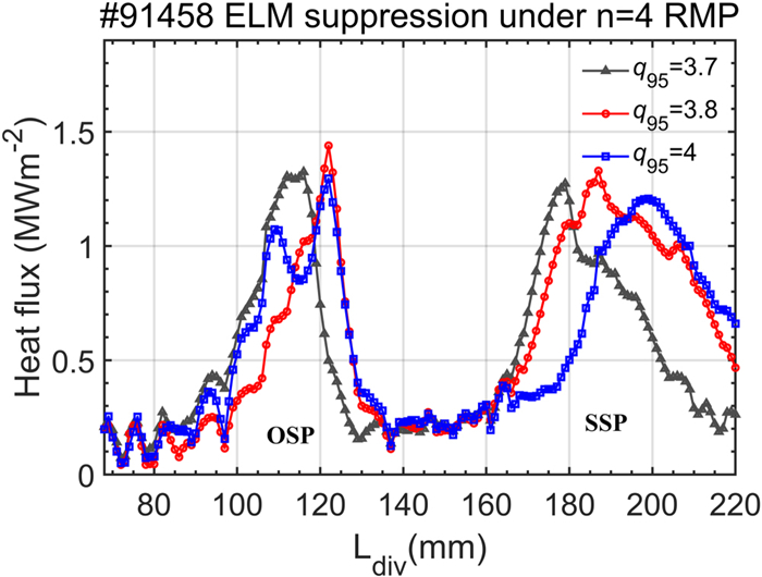
In this paragraph, the preliminary investigation into the effect of q95 on heat flux pattern in H-mode plasma during ELM suppression under RMP is presented. In shot #91458, RMP parameters were set as n = 4, IRMP = 3 kA and ∆φUL = 180°, the q95 ramped down from 4 to 3.6, and ELM suppression was obtained at three q95 windows (around 4, 3.8 and 3.7). The heat flux profiles during ELM suppression at different q95 windows are shown in figure 9. All three profiles show a secondary strike point in the position of 160 to 220 mm (or farther). As q95 decreased, the secondary strike point moved in the direction to divertor corner. This phenomenon is similar to what was reported in JET in L-mode plasma under n = 2 RMP application that q95 scan could drive the magnetic lobes moving in a toroidal direction and resulted in the displacement of the SSP viewed by a fixed IR camera [23]. Except for the geometrical effect in heat flux, the splitting pattern could be also influenced by q95 scan. At q95=4, further splitting occurred at OSP, while at q95=3.7 and 3.8, no similar phenomenon was observed.
Figure
9.
Heat flux profiles during ELM suppression at different q95 windows.
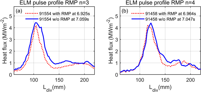
As shown above, the distribution of divertor SHF is effectively influenced by RMP application, and the induced SSP undertakes a considerable part of the heat flux. However, in terms of transient heat flux caused by ELM pulses, no significant changes in heat flux distribution were observed although RMPs (n = 3 or n = 4) were applied. As shown in figure 10, most portion of heat flux condenses at the OSP under both n = 3 and n = 4 RMPs, similar to the situation without RMPs.
Figure
10.
Comparison of transient heat flux distribution at ELM pulses with and without RMP.
Taking advantage of the upgraded infrared thermography diagnostic with a dynamic foveated imager system and the newly developed heat flux calculating code dedicated to W/Cu monoblock divertor with active water-cooling on EAST, characteristics of divertor heat flux in H-mode plasma under high-n RMPs (n = 3 and 4) were investigated. The additional strike point splitting accompanied by ELM suppression is observed under RMPs with both n = 3 and n = 4, implying a significant change in divertor heat flux distribution under ELM suppression. The SSP in heat flux agrees qualitatively with the modeled magnetic footprint. Although RMPs suppress the ELMs, as a cost, they increase the SHF during ELM suppression. The dependence of heat flux on q95 during ELM suppression is preliminarily investigated. Further splitting in OSP is observed at q95=4 during ELM suppression. In terms of ELM pulse, the presence of RMPs both n = 3 and n = 4 shows little influence on transient heat flux distribution, most portion of heat flux condenses at the OSP, similar to the situation without RMP. The upgrade of IR diagnostics is still ongoing for a better investigation into divertor heat flux patterns under RMP applications, and further analysis in detailed physics will be proceeded by performing dedicated simulation via EMC3-EIRENE modeling [44, 45].
Acknowledgments
This work was supported by the National Key Research and Development Program of China (No. 2017YFA0402500), the National MCF Energy R&D Program of China (No. 2019YFE03040000), National Natural Science Foundation of China (Nos. 12005262 and 11975274), the Foundation of President of Hefei Institutes of Physical Science, CAS (No. YZJJ2018QN8), the Anhui Provincial Natural Science Foundation (No. 2108085J06), the Users with Excellence Program of Hefei Science Center CAS (Nos. 2021HSC-UE018 and 2020HSC-UE011), External Cooperation Program of Chinese Academy of Sciences (No. 116134KYSB20180035), Science Foundation of Institute of Plasma Physics, Chinese Academy of Sciences (No. DSJJ-2021-04).
SHI Nan (史楠), GAO Xiang (高翔), JIE Yinxian (揭银先), ZHANG Shoubiao (张寿彪), ZENG Long (曾龙), WANG Erhui (王二辉), YANG Yao (杨耀), LIU Zixi (刘子奚). Far-Infrared Laser Diagnostics in EAST[J]. Plasma Science and Technology, 2011, 13(3): 347-351.
Krieger, K., Brezinsek, S., Coenen, J.W. et al. Scrape-off layer and divertor physics: Chapter 5 of the special issue: on the path to tokamak burning plasma operation. Nuclear Fusion, 2025, 65(4): 043001.
DOI:10.1088/1741-4326/adaf42
2.
Munaretto, S., Kleiner, A., Churchill, R.M. et al. Impact of error fields and error field correction on heat fluxes in SPARC. Nuclear Fusion, 2025, 65(4): 046007.
DOI:10.1088/1741-4326/adb982
3.
Liang, R., Gong, X., Zhang, B. et al. Investigation of divertor heat flux characteristics under the influence of resonant magnetic perturbations on EAST. Nuclear Fusion, 2025, 65(2): 026021.
DOI:10.1088/1741-4326/ad9b38
4.
He, Z., Liu, L., Gao, J. et al. Design of an infrared/visible endoscope system for HL-3 divertor observation. Journal of Instrumentation, 2024, 19(9): P09023.
DOI:10.1088/1748-0221/19/09/P09023
5.
Yang, H., Sun, Y., Jia, M. et al. Dynamic control of divertor heat flux during n = 4 resonant magnetic perturbation edge localized mode suppression by small variation of q 95 in EAST. Nuclear Fusion, 2024, 64(9): 096018.
DOI:10.1088/1741-4326/ad63b8
6.
Navarro, M., Romazanov, J., Kirschner, A. et al. Small resonant magnetic perturbations result in three-dimensional material transport in the fusion plasma edge. Nuclear Fusion, 2024, 64(4): 046015.
DOI:10.1088/1741-4326/ad2b2d
7.
Boinnard, T., Coelho, A.J., Loizu, J. et al. Plasma turbulence simulations in a diverted tokamak with applied resonant magnetic perturbations. Nuclear Fusion, 2023, 63(7): 076005.
DOI:10.1088/1741-4326/acd403

 DownLoad: