Processing math: 0%
Advanced Search+
Liping ZHANG, Jiani LI, Jiangxu FENG, Junyan SU. Effect of spin on the instability of THz plasma waves in field-effect transistors under non-ideal boundary conditions[J]. Plasma Science and Technology, 2023, 25(12): 125002. DOI: 10.1088/2058-6272/ace677
Citation: Liping ZHANG, Jiani LI, Jiangxu FENG, Junyan SU. Effect of spin on the instability of THz plasma waves in field-effect transistors under non-ideal boundary conditions[J]. Plasma Science and Technology, 2023, 25(12): 125002. DOI: 10.1088/2058-6272/ace677

Effect of spin on the instability of THz plasma waves in field-effect transistors under non-ideal boundary conditions

More Information
  • Corresponding author:

    Liping ZHANG, E-mail: zhanglp@lut.edu.cn

  • Received Date: February 20, 2023
  • Revised Date: July 10, 2023
  • Accepted Date: July 10, 2023
  • Available Online: January 04, 2024
  • Published Date: September 14, 2023
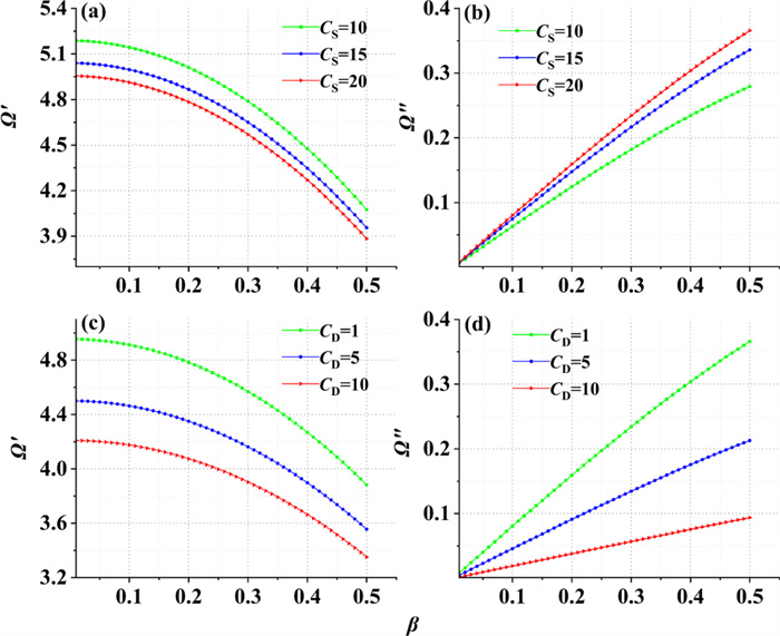
  • Terahertz (THz) radiation can be generated due to the instability of THz plasma waves in field-effect transistors (FETs). In this work, we discuss the instability of THz plasma waves in the channel of FETs with spin and quantum effects under non-ideal boundary conditions. We obtain a linear dispersion relation by using the hydrodynamic equation, Maxwell equation and spin equation. The influence of source capacitance, drain capacitance, spin effects, quantum effects and channel width on the instability of THz plasma waves under the non-ideal boundary conditions is investigated in great detail. The results of numerical simulation show that the THz plasma wave is unstable when the drain capacitance is smaller than the source capacitance; the oscillation frequency with asymmetric boundary conditions is smaller than that under non-ideal boundary conditions; the instability gain of THz plasma waves becomes lower under non-ideal boundary conditions. This finding provides a new idea for finding efficient THz radiation sources and opens up a new mechanism for the development of THz technology.

  • With the development of modern science and technology, terahertz (THz) waves that have not been fully exploited and utilized have attracted more and more people's attention [1, 2]. Today, THz technology is widely used in medical diagnosis [3, 4], space literature [5], security detection [68] and military fields [9]. However, a great leap forward in THz technology can only be achieved by finding efficient THz radiation sources and detectors [10, 11]. In a recent paper by Wang et al, theoretical research and analysis based on the nonlinear optical difference frequency principle show that the THz radiation source with optical parameter effect can effectively generate the THz signal [12]. As early as nearly 30 years ago, Dyakonov and Shur et al had shown that stable DC currents in ballistic field-effect transistors (FETs) could be unstable against the generation of high-frequency plasma waves due to the wave reflection from the device boundaries, which provides a new mechanism of electromagnetic radiation [13]. Aizin et al extended the hydrodynamic model to the case considering stubs, which proved that the instability of plasma in FETs can be controlled by optimizing boundary conditions, the velocity of plasma waves, etc [14].

    Plasma is an ionized gas composed of charged particles as well as neutral particles. The plasma has a very high electrical conductivity, and a strong coupling effect with the electromagnetic field. Plasma waves are caused by a wide variety of collective motion modes. There are elastic restoring forces, thermal pressure, electrostatic force and magnetic field force in plasmas. Because of the interaction among different forces, plasma waves include electromagnetic waves (shear waves) caused by electromagnetic force, static waves (longitudinal waves) caused by electrostatic force, and sound waves caused by thermal pressure. The plasma wave traveling in the FET channel is reflected and amplified when it spreads to the drain. Then the plasma wave becomes unstable, which leads to electromagnetic radiation. When the gate length reaches to submicron, the frequencies of electromagnetic radiation belong to the THz range [12].

    Spin is an intrinsic motion caused by the intrinsic angular momentum of particles, which is an intrinsic property of particles [15]. The contribution of intrinsic spin to the ponderomotive force was explored in a magnetized plasma by using an expression containing both the classical as well as the spin-induced ponderomotive force and the results show that a strong spin polarization in a plasma can be induced by the spin-ponderomotive force [16]. In a recent paper by Brodin [17], the properties of solitary structures were investigated taking into account the microscopic spin properties of the electrons and it is found that the quantum spin effects will induce the solitary structures. Lin et al analyzed the effect of the spin effect on the propagation of electromagnetic waves in any direction in magnetized plasmas, and found that the spin effect has a significant effect on low-frequency modes [18]. A fully consistent quantum-mechanical description of a spin-polarized plasma was constructed by using a generalized matrix Wigner function [19]. There has been many investigations on single-particle spin effects in external field models, for example, intense laser field [20]. In recent years, the study on the excitation of collective modes in spin systems has also aroused curiosity in the scientific community [21, 22]. It is shown by previous studies that there are many novel features and certain advantages in THz radiation in the presence of the spin effect of electrons in the channel of nano-FET.

    Experimental and numerical research has demonstrated that the THz plasma waves become unstable in the presence of the asymmetric boundary conditions that the impedance between the gate and the drain approaches infinity, and the impedance between the gate and the source tends to zero Ohm. In fact, there are some difficulties in the realization of asymmetric boundary conditions, which leads to the attention of other boundary conditions. The instability of THz plasma waves was developed using a compact model with tunable narrow-channel regions with an increased width, and the plasmonic boundary conditions are matched at the interfaces between different regions in the channel [14]. In 2018 [23], by linearization of hydrodynamic equations describing the collective behavior of two-dimensional electron gas in the channel of high electron mobility transistor, the THz radiation was firstly explored with the impact of non-ideal termination impedances at the source and the drain, and numerical results showed that the DS instability would be affected by non-ideal boundary conditions. However, to the authors' best knowledge, very few publications address the issue of the characteristics of THz plasma waves traveling in the channel of FETs with non-ideal boundary conditions, spin effects and quantum effects.

    In our work, the instability of THz plasma waves in FETs under the non-ideal boundary conditions is investigated with the joint action of spin effects, quantum effects and the external magnetic field. In order to study the features of the THz plasma waves, we started from the quantum fluid dynamics equation and spin equation, and obtained dispersion relation with non-ideal boundary conditions and quantum effects. The influences of drain capacitance, source capacitance, spin effects, quantum effect, channel width and electron drift velocity on the instability of plasma THz wave in FETs under the joint action of non-ideal boundary conditions are discussed in detail.

    With the rapid development of nanotechnology, the characteristic size of electronic devices is becoming smaller and smaller, that is, from the micron to nanometer. The characteristic size of traditional semiconductor devices is in the order of microns, and the particle property of electrons is dominant. When the characteristic size of the device is equal to or smaller than the de Broglie wavelength of electrons or the mean free path of electrons, and the volatility of electrons is dominant, and then we get all sorts of quantum effects. At Fermi temperature, the electron state changes from the Maxwell–Boltzmann distribution to the Fermi–Dirac distribution [24]. In this case, the motion of the electron must be described using the equations of quantum fluid mechanics with quantum effects. So, in order to investigate the instability of THz plasma waves with spin effects and quantum effects, the collective behavior of electron fluid is governed by the quantum fluid dynamics equations [25, 26] with spin effects [27, 28] and Maxwell's equations:

    nt+·(nv (1)
    v t+ v· v=- em E+ v× B - 1mnP + ħ2 2m2 1 n 2 n + 2μ mħ B· S (2)
    × E=- B t (3)
    × B= μ 0 J+ ε 0 E t+ J m (4)
    · E=- e ε 0 n (5)
    P=2 T Fe n (6)

    where n represents the number density of the electrons, v is the fluid velocity of the electrons, e represents the charge of the electron, m represents the mass of the electron; E and B represent the electric field strength and the magnetic field strength, respectively; μ represents Bohr magnetic moment, the smallest element of the Bohr magnetic moment is the Bohr magneton. P stands for quantum Fermi pressure; μ 0 and ϵ 0 are used to represent the permeability and electrical conductivity in vacuum, respectively; and the current density J is equal to J=-e n 0 v; electron spin-magnetization current density J m =× M (here M is the spin-magnetization vector in the macroscopic state.), and M= n e u B 2 k B T Fe B (here the μ B = eħ 2m represents the Bohr magneton, T Fe represents Fermi temperature, k B indicates the Boltzmann constant, n e represents the electron gas density at the Fermi temperature.).

    The evolution equation describing the spin effects in quantum plasma is as follows:

    d s dt= 2 μ B ħ S× B . (7)

    Because the scale of the electron is larger than the Larmor radius of the electron in the magnetohydrodynamic model, we can ignore the quadratic term of the spin S in the spin evolution equation. For the lower order, when it is far below the cyclotron frequency of the electron, the inertia term of the electron can also be ignored and S+ B=0 can be obtained, so we can get the spin expression:

    S=- ħ2 η μ B B 0 k B T e B^ (8)

    here, η x = tanh x x= μ B B 0 K B T e is the Langevin parameter, which is a physical quantity describing the size of the spin. We see from the spin formula that spin is a function of the Langevin parameter. The Langevin parameter depends on the magnetic field, which is a variable when the magnetic field changes. T e represents the electron temperature, B 0 is the strength of the external magnetic field.

    To study the stability of THZ plasma waves, we set n= n 0 + n 1 , v x = v 0 + v x 1 , v y = v y 1 , E x = E x 1 , E y = E y 1 , B= B 0 + B z1 , n 0 , v 0 , v 0 are constants. In order to linearize equations (1)–(6), we set n 1 , v x1 , v y1 ~ exp -iωt+ikx+iqy , where k and q are the wave vectors along the X-axis and Y-axis directions, respectively. The linearized equations can be written as:

    k v x1 +q v y1 n 0 + k v 0 -ω n 1 =0 (9)
    k v 0 -ω v x1 -i ω ce v y1 =i em E x1 - v Fe 2 n 0 k+ ħ2 4m2 n 0 k k2 +q2 n 1 - μ B η x mk B z1 (10)
    k v 0 -ω v y1 +i ω ce v 0 +i ω ce v x1 = i em E y1 - v Fe 2 n 0 q+ ħ2 4m2 n 0 q k2 +q2 n 1 - i e v 0 m+ μ B η x mq B z1 (11)
    q2 - ω2 χc2 E x1 -kq E y1 =- μ 0 e n 0 χiω v x1 (12)
    k2 - ω2 χc2 E y1 -kq E x1 =- μ 0 e n 0 χiω v y1 (13)

    where ω ce = e B 0 m, v Fe = 2 T Fe m , B z1 = 1ω k E y1 -q E x1 .

    To study the features of THz plasma waves simply, the linearized expressions of equations (9)–(13) are as follows,

    K v~ x1 +Q v~ y1 + Kβ-Ω n~ 1 =0 (14)
    Kβ-Ω v~ x1 -i ω~ ce v~ y1 = i+ KQ μ~ B η x Ω E~ x1 - K2 μ~ B η x Ω E~ y1 - K+HK K2 +Q2 n~ 1 (15)
    Kβ-Ω v~ y1 +i ω~ ce v~ x1 = i- iβKΩ- KQ μ~ B η x Ω E~ y1 + iβQΩ+ Q2 μ~ B η x Ω E~ x1 - Q+HQ K2 +Q2 n~ 1 (16)
    Q2 c~2 - Ω2 χ E~ x1 -KQ c~2 E~ y1 =- ω pe ~2 χiΩ v~ x1 (17)
    K2 c~2 - Ω2 χ E~ y1 -KQ c~2 E~ x1 =- ω pe ~2 χiΩ v~ y1 (18)

    where K=kL, Q=qL, Ω= ωL v Fe , β= v 0 v Fe , v~ x1 = v x1 v Fe , v~ y1 = v y1 v Fe , ω~ ce = ω ce L v Fe , E~ x1 = E x1 eL m v Fe 2 , E~ y1 = E y1 eL m v Fe 2 , H= ħ2 4m2 1 v Fe 2 L2 , n~ 1 = n 1 n 0 , c~= c v Fe , χ1- n 0 μ 0 μ B 2 k B T e , ω pe = e2 n 0 m ε 0 12 , ω pe ~= ω pe L v Fe .

    According to equations (14)–(18), we obtain the dimensionless dispersion relation:

    Kβ-Ω (HK4 Ω ω pe ~2 -Ω2 +K2 Ω((1+2HQ2 -β2 + ω~ ce η μ~ B ) ω pe ~2 + -1-2HQ2 +β2 Ω2 - Kβ ω pe ~4 -3 ω pe ~2 Ω2 +2Ω4 + c~2 K2 +Q2 × χ HK4 Ω+K2 1+2HQ2 -β2 Ω-Kβ × ω pe ~2 -2Ω2 +Ω ω~ ce 2 +Q2 +HQ4 + ω pe ~2 -Ω2 + Ω i ω~ ce Qβ ω pe ~2 + ω pe ~4 - ω~ ce 2 Ω2 -2 ω pe ~2 Ω2 +Ω4 + HQ4 ω pe ~2 -Ω2 +Q2 ω pe ~2 + ω~ ce ημ ω pe ~2 -Ω2 ) = 0. (19)

    In equation (19), Ω=Ω'+i Ω'', Ω' represents the plasma oscillation frequency, and Ω'' represents the instability gain of the THz plasma waves. If the value of the instability gain is greater than zero, the THz plasma waves are unstable. Instead, if the value of the instability gain is less than zero, the THz plasma waves are stable. Furthermore, K represents the dimensionless wave vector in the X-direction, and Q represents the dimensionless wave vector in the Y-direction, H represents the contribution of the quantum effect, ω pe ~ is the dimensionless plasma frequency. η is the Langevin parameter, which represents the spin distribution under thermal equilibrium. ω~ ce is used to characterize the dimensionless electron cyclotron frequency of the magnetic field.

    From equation (19), we can obtain the seven roots of K. Since the waves propagating from the source to the drain will be reflected, the incident wave and the reflected wave are mutually symmetrical, so we should choose two symmetric roots K 1 and K 2 . The solution of linearized equation (9) takes the form:

    V ω = 1WC kω I ω = 1WCω k 1 I 1 e i k 1 x+ k 2 I 2 e i k 2 x (20)
    I ω = I 1 e i k 1 x+ I 2 e i k 2 x (21)

    here, I ω =-eW v 0 n 1 + n 0 v x1 is the channel current, the voltage distribution is V ω =δ φ ω , W is used to denote the width of the channel.

    DS instable theory indicated that the THz plasma waves become unstable in the presence of the asymmetric boundary conditions that the impedance between the gate and the drain approaches infinity, and the impedance between the gate and the source tends to zero Ohm. Then, Mona et al have come up with other boundary conditions that source capacitance and drain capacitance are attached in high electron mobility transistors [23]. These boundary conditions agree with equations V 0,t =-i Z S I 0,t and V L,t =i Z D I L,t , which are also called non-ideal boundary conditions. (Here Z S and Z D indicate source and drain impedance, respectively.) The non-ideal boundary conditions can be written in the form:

    I 0 =- C S V 0 t (22)
    I L = C D V L t (23)

    here C S is the source capacitance, C D is the drain capacitance, and L is the channel length.

    According to equations (20)–(23), we obtain:

    e i k 1 - k 2 L= CW-i C S k 1 CW+i C D k 2 CW+i C D k 1 CW-i C S k 2 (24)

    We shall write the above expression as:

    e i K 1 - K 2 = W~-i K 1 C S ~ W~+i K 2 C D ~ W~+i K 1 C D ~ W~-i K 2 C S ~ (25)

    here, K 1 = k 1 L, K 2 = k 2 L, C S ~= C S CL2 , C D ~= C D CL2 .

    In order to investigate the propagation of THz plasma waves in the channel of FET with the combined contribution of spin effects, the quantum effects and non-ideal boundary conditions, we numerically solve equations (19) and (25). The features of instability of THz plasma waves are discussed in two different cases.

    Case 1 Source capacitance is greater than the drain capacitor

    Figure 1 shows the trend of the oscillation frequency Ω' and the instability gain Ω'' of the THz plasma waves changing with the drift velocity β for different C S and C D , when the source capacitance C S is larger than the gate capacitance C D . As shown in figures 1(a) and (c), the plasma oscillation frequency decreases with increasing drift velocity β, and when the drift velocity β is certain, the oscillation frequency of the THz plasma waves decreases with the increasing source capacitance C S and drain capacitance C D . From figure 1(b), it can be seen that the instability gain increases with the drift velocity β; when the drift velocity β is a fixed value, the larger the source capacitance C S , the greater the instability gain increases; and the effect of C S on the instability gain is not obvious when β is small, however, as β continuously increases, the effect of C S on the instability gain becomes increasingly apparent. As can be seen from figure 1(d), the instability gain of the THz plasma waves increases as β grows. When β is a fixed value, the larger the drain capacitance C D , the smaller the instability gain. As we know, plasma waves propagating along the channel of FET are reflected from the drain and amplified, then become unstable. When plasma waves propagate along the channel, there will be a change in energy due to the variation of physical factors. The energy loss will reduce the instability of plasma waves. So, we can conclude that the increase in source capacitance will reduce the energy loss, and the increase in drain capacitance will strengthen the energy loss.

    Figure  1.  Trend diagram of Ω' and Ω'' versus β for different C S , C D with q=0.1, χ=0.5, ω ce =0.3,c=1000,η=0.1,μ =0.4, ω pe =0.6,H=0.001,W=30, C D =1, C S =20.

    The characteristics of FET will change in the presence of the quantum effects. Figure 2 shows the effect of quantum effects H on the oscillation frequency and the instability gain of the THz plasma waves when the source capacitance C S is larger than the drain capacitor C D . It can be seen from figure 2(a) that the oscillation frequency increases with quantum effect. Figure 2(b) shows that the instability gain increases with increasing drift velocity β, when the quantum effects H is certain; and if the drift velocity β is a constant value, the larger the quantum effects H, the greater the instability gain. The increase of instability gain represents the increase of radiant power. It is clear that quantum effects can reduce the energy loss of the plasma during the oscillation. As the size of electronic devices gets smaller and smaller, quantum effects become more pronounced. We can change the oscillation frequency and instability gain of the THz plasma waves by changing the size of the device. This is consistent with the results of Knap et al, that the oscillation frequency increases as the device size decreases [29].

    Figure  2.  Trend diagram of Ω' and Ω'' versus β for different H with q=0.1,χ=0.5, ω ce =0.3,c=1000,η=0.1,μ = 0.4, ω pe =0.6,W=30, C S =20, C D =1.

    Figure 3 shows the effect of the channel width W on the oscillation frequency and the instability gain when the source capacitance C S is larger than the drain capacitor C D . From figure 3(a), we can find that the plasma oscillation frequency increases with the channel width. During our discussion, we found that the influence of the channel width W on the instability gain is complicated. Such cases are shown in figure 3(b). Figure 3(b) depicts that for a certain β, the instability gain increases firstly and after crossing a critical value in terms of β it stars decreasing gradually. From the above results, it can be obtained that the current will become unstable in the channel of FET with non-ideal boundary conditions and there is the emission of THz waves when the source capacitance is larger than the drain capacitor.

    Figure  3.  Trend diagram of Ω' and Ω'' versus W and β with q=0.1,χ=0.5, ω ce =0.3,c=1000,η=0.1,μ = 0.4, ω pe =0.6,H=0.001, C S =20, C D =1.

    Figure 4 shows the effect of the spin effect on the oscillation frequency and the instability gain when the source capacitance is larger than the drain capacitor. We can see from figure 4 that the oscillation frequency and instability gain with the spin effect are larger than that without the spin effect. That is, the spin can not only enhance the oscillation frequency but also increase the instability gain. Obviously, the presence of the spin reduces the energy loss during the plasma oscillation and amplification.

    Figure  4.  Trend diagram of Ω' and Ω'' versus β with and without spin effects with q=0.1,χ=0.5, ω ce =0.3,c=1000,H=0.001, ω pe = 0.6,W=30, C S =20, C D =1.

    Since η affects the spin value, we change η to observe the change of oscillation frequency and instability gain. The results show that the size of η has a very small effect on the oscillation frequency and the instability. Compared with the results in [30], the oscillation frequency and instability gain of THz plasma wave increase with increasing η. In other words, under non-ideal boundary conditions, the oscillation frequency and instability gain of THz plasma waves increase with the appearance of spin, but the size of spin does not have a significant effect on the oscillation frequency and instability gain. However, under asymmetric boundary conditions, the effect of the size of the spin on the oscillation frequency and instability gain is evident.

    Case 2 Drain capacitor is greater than the source capacitance.

    Figures 58 give an example of the instability of THz plasma waves in the channel of FET with spin effects, quantum effects and non-ideal boundary conditions when the source capacitance C S is smaller than the drain capacitance C D . As can be seen from figures 58, in two cases, that is, the source capacitance is smaller than the drain capacitance, and the source capacitance is bigger than the drain capacitance, the influence of spin effects, quantum effects, the drain capacitance, the source capacitance and the width of the channel on the plasma oscillation frequency is the same. As shown in figures 5(b), 6(b), 7(b) and 8(b) when the source capacitance C S is less than the drain capacitance C D , the value of the resulting instability gain Ω'' is less than zero, which indicates that the THz wave oscillation is stable in this case. The larger the absolute value of Ω'' means the more stable THz plasma waves. From figure 6(b), we can see that the value of the instability gain is negative when the source capacitance is smaller than the drain capacitor, indicating that the oscillation of the THz wave is stable in this case. As the quantum effect increases, the instability gain becomes small and the THz waves become more stable. That is, in this case, THz radiations do not occur. When the source capacitance increases the instability of THz plasma waves slows down.

    Figure  5.  Trend diagram of Ω' and Ω'' versus β for different C S , C D with q=0.1,χ=0.5, ω ce =0.3,c=1000,η=0.1,μ = 0.4, ω pe =0.6,H=0.001,W=30, C D =20, C S =1.
    Figure  6.  Trend diagram of Ω' and Ω'' versus β for different H with ( q=0.1,χ=0.5, ω ce =0.3,c=1000,η=0.1,μ = 0.4, ω pe =0.6,W=30, C S =1, C D =20 ).
    Figure  7.  Trend diagram of Ω' and Ω'' versus W and β with q =0.1,χ=0.5, ω ce =0.3,c=1000,η=0.1,μ = 0.4, ω pe =0.6,H=0.001, C S =1, C D =20.
    Figure  8.  Trend diagram of Ω' and Ω'' versus β with and without spin effects with q=0.1,χ=0.5, ω ce =0.3,c=1000,H=0.001, ω pe =0.6,W=30, C S =1, C D =20.

    Similarly, as shown in figures 7(b) and 8(b), the effects of the channel width W and spin on the instability gain are indicated, and the instability gain in this case is less than zero, which indicates that the THz wave oscillation is stable in this case.

    Under asymmetric boundary conditions, the source impedance Z S =0 and drain impedance Z D =. However, under non-ideal boundary conditions, the Z S and Z D take the finite values. These impedances are the result of the presence of capacitance at the source or drain. The larger induced impedance of the bonding wires is effectively shunted by these impedances, and defines the termination impedance at both ends of the plasma cavity [31]. Figure 9 shows the effect of two different boundary conditions, namely, asymmetric boundary conditions and non-ideal boundary conditions, on the oscillation frequency and the instability gain of the plasma THz waves. From figure 9(a), we can see that the plasma oscillation frequency in the non-ideal boundary conditions is larger than that in the asymmetric boundary conditions. It is clear that the change in the source and drain impedance caused the change in the oscillation frequency. As shown in figure 9(b), the instability gain in asymmetric boundary conditions is higher than that in the non-ideal boundary conditions. Thus, under non-ideal boundary conditions, finite source and drain impedances suppress instability. That is, non-ideal boundary conditions can increase the oscillation frequency of the plasma THz waves, while asymmetric boundary conditions can improve the instability gain of the plasma THz waves.

    Figure  9.  Trend diagram of Ω' and Ω'' versus β for asymmetric boundary conditions and non-ideal boundary conditions with q=0.1,χ=0.5, ω ce =0.1,c=1000,η=0.1,μ=0.4, ω pe = 0.6,H =0.001,W=30, C D =1, C S =20.

    In conclusion, the linear characteristics of THz plasma waves in the channel of FET with non-ideal boundary conditions are considered by linearizing Maxwell's equations and the quantum fluid dynamics equations containing the spin effect and quantum effect. Summing up the results, it can be concluded that in a FET, if the source capacitance is greater than the drain capacitance, the THz plasma waves become unstable, which indicates that there is THz emission in this case. When the drift velocity is fixed, the oscillation frequency increases with the increase in quantum effect, and decreases with the increase of source capacitance and drain capacitance, while the instability gain increases with the increase of source capacitance and quantum effect, and decreases with the increase of drain capacitance. In contrast, if the drain capacitance is greater than the source capacitance, the value of the instability gain is less than zero, that is, the THz plasma waves are stable. Meanwhile, the quantum effect and spin effect enhance the emission of THz waves, and the boundary conditions can affect the oscillation frequency and the instability gain of plasma THz waves. In [30], the effects of spin, quantum effects, drift velocity and other factors on the oscillation frequency and instability gain of THz plasma waves are investigated under asymmetric boundary conditions. Compared with the results in [30], we found that the influence of boundary conditions is very important. The oscillation frequency with asymmetric boundary conditions is smaller than that under non-ideal boundary conditions, but the instability gain of THz plasma waves becomes lower under non-ideal boundary conditions. The findings suggest that this study could also be useful for the development of THz source and detector.

    This work was funded by National Natural Science Foundation of China (No. 12065015) and the Hongliu First-level Discipline Construction Project of Lanzhou University of Technology.

  • [1]
    Siegel P H 2002 IEEE Trans. Microwave Theory Tech. 50 910 doi: 10.1109/22.989974
    [2]
    Hangyo M 2015 Jpn. J. Appl. Phys. 54 120101 doi: 10.7567/JJAP.54.120101
    [3]
    Siegel P H 2004 IEEE Trans. Microwave Theory Tech. 52 2438 doi: 10.1109/TMTT.2004.835916
    [4]
    Arnone D D et al 1999 Proc. SPIE 3828 209 doi: 10.1117/12.361037
    [5]
    De Maagt P, Bolivar P H and Mann C 2005 Terahertz science, engineering and systems-from space to Earth applications Encyclopedia of RF and Microwave Engineering ed K Chang (Hoboken, NJ: Wiley)(https://doi.org/10.1002/0471654507.eme518)
    [6]
    Qin J Y, Ying Y B and Xie L J 2013 Appl. Spectrosc. Rev. 48 439 doi: 10.1080/05704928.2012.745418
    [7]
    Wang K Q, Sun D W and Pu H B 2017 Trends Food Sci. Technol. 67 93 doi: 10.1016/j.tifs.2017.06.001
    [8]
    Afsah-Hejri L et al 2019 Compr. Rev. Food Sci. Food. Saf. 18 1563 doi: 10.1111/1541-4337.12490
    [9]
    Ergün S and Sönmez S 2015 J. Mil. Information Sci. 3 13 doi: 10.17858/jmisci.58124
    [10]
    Bratman V L et al 2006 AIP Conf. Proc. 807 356-366 doi: 10.1063/1.2158799
    [11]
    Liu Y et al 2007 Phys. Rev. Lett. 99 135002 doi: 10.1103/PhysRevLett.99.135002
    [12]
    Dyakonov M and Shur M 1993 Phys. Rev. Lett. 71 2465 doi: 10.1103/PhysRevLett.71.2465
    [13]
    Li Z Y et al 2017 Opt. Laser Technol. 96 65 doi: 10.1016/j.optlastec.2017.05.014
    [14]
    Aizin G R, Mikalopas J and Shur M 2018 Phys. Rev. Appl. 10 064018 doi: 10.1103/PhysRevApplied.10.064018
    [15]
    Messiah A 2014 Quantum Mechanics(New York: Dover)
    [16]
    Brodin G, Misra A P and Marklund M 2010 Phys. Rev. Lett. 105 105004 doi: 10.1103/PhysRevLett.105.105004
    [17]
    Brodin G and Marklund M 2007 Phys. Plasmas 14 112107 doi: 10.1063/1.2793744
    [18]
    Hu Q L et al 2016 Phys. Plasmas 23 112113 doi: 10.1063/1.4967760
    [19]
    Zhang W Y and Balescu R 1988 J. Plasma Phys. 40 199 doi: 10.1017/S0022377800013222
    [20]
    Walser M W et al 2002 Phys. Rev. A 65 043410 doi: 10.1103/PhysRevA.65.043410
    [21]
    Blum F A 1971 Phys. Rev. B 3 2258 doi: 10.1103/PhysRevB.3.2258
    [22]
    San Roman J, Roso L and Plaja L 2003 J. Phys. B: At. Mol. Opt. Phys. 37 435 doi: 10.1088/0953-4075/37/2/011
    [23]
    Nafari M, Aizin G R and Jornet J M 2018 Phys. Rev. Appl. 10 064025 doi: 10.1103/PhysRevApplied.10.064018
    [24]
    Manfredi G 2005 Fields Inst. Commun. 46 263 doi: 10.1103/PhysRevApplied.10.064025
    [25]
    Crouseilles N, Hervieux P A and Manfredi G 2008 Phys. Rev. B 78 155412
    [26]
    Manfredi G and Haas F 2001 Phys. Rev. B 64 075316 doi: 10.1103/PhysRevB.78.155412
    [27]
    Brodin G and Marklund M 2007 New J. Phys. 9 277 doi: 10.1088/1367-2630/9/8/277
    [28]
    Holland P R 1993 The Quantum Theory of Motion. (Cambridge: Cambridge University Press) (http://www.w3.org/1999/xlink" href="https://doi.org/10.1017/CBO9780511622687">https://doi.org/10.1017/CBO9780511622687)
    [29]
    Knap W et al 2008 J. Phys. Condens. Matter 20 384205 doi: 10.1088/0953-8984/20/38/384205
    [30]
    Liu C X, Zhang L P and Feng J X 2021 AIP Adv. 11 085207 doi: 10.1063/5.0056132
    [31]
    Svintsov D 2018 Phys. Rev. Appl. 10 024037 doi: 10.1103/PhysRevApplied.10.024037

Catalog

    Figures(9)

    Article views (29) PDF downloads (12) Cited by()

    /

    DownLoad:  Full-Size Img  PowerPoint
    Return
    Return