Haiying LI, Jiachen TONG, Wei DING, Bin XU, Lu BAI. Transmission characteristics of terahertz Bessel vortex beams through a multi-layered anisotropic magnetized plasma slab[J]. Plasma Science and Technology, 2022, 24(3): 035004. DOI: 10.1088/2058-6272/ac3ad7
Citation:
Haiying LI, Jiachen TONG, Wei DING, Bin XU, Lu BAI. Transmission characteristics of terahertz Bessel vortex beams through a multi-layered anisotropic magnetized plasma slab[J]. Plasma Science and Technology, 2022, 24(3): 035004. DOI: 10.1088/2058-6272/ac3ad7
Haiying LI, Jiachen TONG, Wei DING, Bin XU, Lu BAI. Transmission characteristics of terahertz Bessel vortex beams through a multi-layered anisotropic magnetized plasma slab[J]. Plasma Science and Technology, 2022, 24(3): 035004. DOI: 10.1088/2058-6272/ac3ad7
Citation:
Haiying LI, Jiachen TONG, Wei DING, Bin XU, Lu BAI. Transmission characteristics of terahertz Bessel vortex beams through a multi-layered anisotropic magnetized plasma slab[J]. Plasma Science and Technology, 2022, 24(3): 035004. DOI: 10.1088/2058-6272/ac3ad7
The transmission of terahertz (THz) Bessel vortex beams through a multi-layered anisotropic magnetized plasma slab is investigated by using a hybrid method of cylindrical vector wave functions (CVWFs) and Fourier transform. On the basis of the electromagnetic boundary conditions on each interface, a cascade form of expansion coefficients of the reflected and transmitted fields is obtained. Taking a double Gaussian distribution of the plasma density as an example, the influences of the applied magnetic field, the incident angle and polarization mode of the incident beams on the magnitude, OAM mode and polarization of the transmitted beams are analyzed in detail. The results indicate that the applied magnetic field has a major effect upon the polarization state of the transmitted fields but not upon the transmitted OAM spectrum. The incident angle has a powerful influence upon both the amplitude profile and the OAM spectrum of the transmitted beam. Furthermore, for multiple coaxial vortex beams, an increase of the maximum value of the plasma density causes more remarkable distortion of both the profile and OAM spectrum of the transmitted beam. This research makes a stable foundation for the THz OAM multiplexing/demultiplexing technology in a magnetized plasma environment.
THz vortex beams with OAM (orbital angular momentum), have potential applications in many fields, including THz wireless communication [1–4], super-resolution imaging [5], manipulating matters [6], spectroscopic probe of magnetism in matter [7], and so have attracted the attention of many researchers. Similar to optical OAM, by using the generation principles of wave-front modulators and THz hologram technology, a large number of methods have been proposed, such as diffractive elements [8], metasurfaces [9, 10], an ultrathin planar THz vortex phase plate [11], a spiral phase plate [5, 12], THz computer-generated holograms [13] and so on. Moreover, based on the nonlinear effects of plasma [14], THz vortex can be generated by beating two vortex lasers in rippled plasma [15, 16], and by transferring the OAM from the plasma vortex to the emitted THz wave [17–19]. Also using plasma, a THz pulse with OAM is obtained by employing two twisted input lasers [20]. What is more, some multiplexing/demultiplexing systems of THz OAM also have been demonstrated successfully [21–23], and the results indicate the potential of THz OAM in improving channel capacity.
Specifically, it is worth noting that the impact of propagation environment on THz OAM communication performance is one of the key points. According to this, Zhao et al discussed the modal coupling and crosstalk of multiple THz OAM beams propagating in turbulence, and the results show that the divergence and turbulence effects in the THz regime are different from those in the mm-wave and optical regime [1]. As we all know, the plasma environment widely exists in nature, laboratory and industry, such as ionosphere, interstellar medium, and laser fusion. In particular, the effects of plasma sheath, which is generated during the re-entering process of spacecraft, on tracking, telemetry and control (TT&C) communication have become a key problem in the application of hypersonic vehicles. In order to overcome the 'blackout' phenomenon caused by plasma sheath, many ways have been proposed, for example, applying a magnetic field [24, 25]. Meanwhile, owing to its good penetrability, THz wave is proved to be a new method to solve 'blackout'. Many studies on the propagation characteristics of THz waves in plasma sheath [26–29] have been reported. Further, considering the existing ablative particles, the sheath can be seen as dusty plasma environments, and the effects of dusty plasma with the ceramic substrate on the propagation of THz waves have been analyzed by the scattering matrix method (SMM) [30]. After discussing the effects of the inhomogeneity of plasma sheath, the incident direction, the flight speed, as well as the applied magnetic field, the conclusion shows that THz waves may raise the propagation performance of electromagnetic waves in plasma sheath. Therefore, in light of the application value of the new dimension-OAM in increasing channel capacity, it is prospective to explore the transmission of THz vortex beams in a plasma environment. In the earlier stage, with the help of the plane wave angular spectrum expansion method, we have carried out the transmission of a THz vortex beam and OAM crosstalk of multiple coaxial THz vortex beams in an unmagnetized plasma slab [31, 32]; however, for magnetized plasma, this method is not applicable. Thus, combining the vector wave function expansion with Fourier transform representation of an electromagnetic wave in magnetized plasma, we have proposed a new method to solve the transmission of a THz vortex beam passing through uniform magnetized plasma [33]. Whereas, for most environments, the distribution of the plasma density is nonuniform, which means that the transmission in non-uniform magnetized plasma is worthy of further study. This is what the work focuses on.
In this work, the typical non-diffraction Bessel vortex beam is chosen as the incident source, and the theoretical model is presented in section 2, including the expansion of electromagnetic fields in plasma regions in terms of cylindrical vector wave functions (CVWFs) and Fourier transform, and derivation of a cascade form of expansion coefficients. Section 3 discusses the effects of the applied magnetized field, the incident angle and the polarization mode upon the characteristics of the transmitted fields. Finally, section 4 summarizes the major conclusions.
2.
Theoretical model
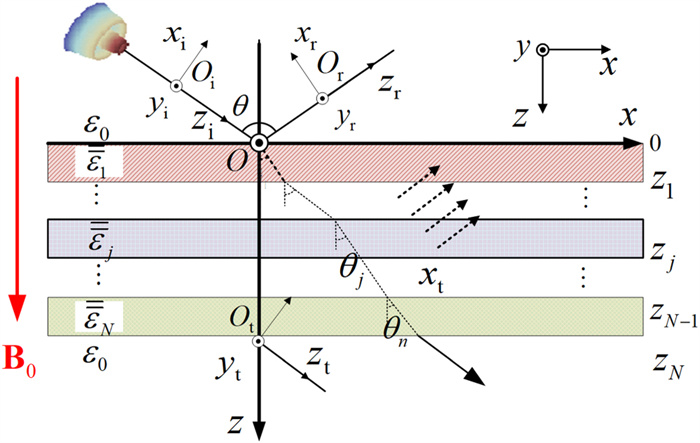
Figure 1 depicts a THz Bessel vortex beam impinging upon a multi-layered magnetized plasma slab, where the global coordinate system Oxyz is based on the plasma slab. In order to describe the incident, reflected and transmitted beams clearly, three local coordinate systems Oßxßyßzß (ß=i,r,ort) are established, in which the positive zß-axes are along the central axes of the corresponding beams. The incident angle θ is the angle between the zi and z axes. The non-uniform magnetized plasma slab is split into N layers, and the thickness of the jth layer of the magnetized plasma slab is dj=zj-zj-1. Additionally, the time factor exp(-iωt) of the electromagnetic field is omitted.
Figure
1.
Schematic diagram of a Bessel vortex beam incident upon a multi-layered magnetized plasma slab.
Assuming the direction of the applied magnetic field B0 is along the positive z-axis, then, the permittivity tensor of plasma in the jth layer is represented as
=εj=[εj,1−εj,20εj,2εj,1000εj,3]
(1)
where εj,1=ε0(1+ω2j,p/ω(ω+ivj,e)[ω2c-(ω+ivj,e)2]),εj,2=ε0(iωc·ω2j,p/ω[ω2c-(ω+ivj,e)2]),εj,3=ε0(1-ω2j,p/ω(ω+ivj,e)),ωc,νj,e,ωj,p and ω are the cyclotron frequency, the collision frequency, the angular plasma frequency and the angular frequency of the incident wave, respectively. ε0 is the permittivity of vacuum, and i is the imaginary unit.
2.1
Description of the incident THz Bessel vortex beam
The expression of a vector Bessel vortex beam is presented in terms of angular spectrum decomposition method as follows [34]:
E(r)=∫2π0E0Q(α,φ)|α=α0eilφeik0·rdφ,
(2)
where E0 and k0 are the amplitude and the wave vector of the electric field component of the plane waves propagating over the cone with the half-angle α0 and the azimuthal angle φ, respectively. Q(α,φ) is the vector complex polarization function, and l is the topological charge (TC) of the vortex beam.
As a THz Bessel vortex beam is incident obliquely on the plasma slab, making use of CVWFs (m(1)mλ0,n(1)mλ0) [35] in the global coordinate system, the electromagnetic field vectors of the incident beam can be expanded and written as:
where k0=λ0ˆρ+h0ˆz,|k0|=k0,λ0=k0sinζ,h0=k0cosζ,ζ represents the angle between k0 and the positive z-axis, μ0 is the permeability, and the superscripts inc and (1) stand for the incident beam and the first kind of Bessel function respectively. The coefficients Aincm(ζ),Bincm(ζ) are derived and shown as:
Aincm(ζ)=∞∑n=|m|[a'
(5)
(6)
here and are the expansion coefficients of the Bessel vortex beam in terms of spherical vector wave functions in the global coordinate system [36]. and are the angle functions, where is the associated Legendre function. In the following analysis, only the integral interval is meaningful.
2.2
CVWFs expansion of electromagnetic fields in anisotropic magnetized plasma
In the jth layer of a multi-layered magnetized plasma slab, the wave equation of the electric field in the source-free region is
(7)
By using Fourier transform, the electric field in equation (7) can be shown as
(8)
After a series of analysis on eigenvalue and eigenvector [37], the electric field in plasma can be expressed as
(9)
where is the eigenvector, which is corresponding to the eigenvalue The subscript indicates that the integral is solved in the k-domain coordinate system. If we expand to equation (9) can be rewritten as
(10)
Here, the eigenvalues are where and
By expanding in terms of CVWFs (), and through some reasonable simplification, equation (10) is expressed as
(11)
where, and The expansion coefficients are
(12)
In order to describe the transmission of the electromagnetic waves in each layer of the magnetized plasma slab more vividly, we decompose equation (11) into two parts:
(13)
(14)
where equations (13) and (14) denote the downgoing and the upgoing waves in each plasma layer, respectively. Note that the variable is replaced by and are the unknown expanding coefficients.
2.3
Reflected and transmitted beams by a multi-layered magnetized plasma slab
Similar to equations (3) and (4), the electromagnetic fields of the reflected beam by a multi-layered magnetized plasma slab can be expanded as
(15)
(16)
and the electromagnetic fields of the transmitted beam are
(17)
(18)
where and are the unknown expansion coefficients of the reflected and transmitted beams, respectively.
Based on the boundary conditions of the electromagnetic fields on every interface, we have
(19)
(20)
(21)
Substituting equations (3), (4) and (13)–(18) into equations (19)–(21), the relationships of expansion coefficients are obtained as follows:
(22)
(23)
(24)
where the expression of the coefficient matrices is shown in the appendix. After a series of simplifications, the cascade form of the unknown expansion coefficients can be obtained and devoted by
(25)
Let us make
(26)
Then the expansion coefficients of the reflected and transmitted beams are
(27)
when the inhomogeneous magnetized plasma slab degenerates into a homogeneous one, the results of equation (27) are in conformity with that in [36].
2.4
OAM spectrum of the distorted vortex beam
Owing to the effects of the magnetized plasma slab, the vorticity of the incident Bessel vortex beam will be distorted. For example, except the dominant OAM state (whose TC is the same as that of the incident beam), some other OAM states are often derived in the transmitted beam. Normally, the weight distribution of the OAM states of the distorted beam is used to describe the vorticity of the transmitted beam, and the weight of each OAM state is defined as [33]:
(28)
where is the electromagnetic field energy of the OAM state
3.
Results and discussion
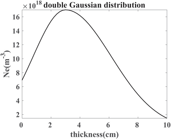
Considering that the plasma density of the slab is double Gaussian distribution, that is
(29)
where, and represent the density gradient in ascending and descending processes, respectively. is the maximum value of the plasma density, while is the corresponding coordinate value. Figure 2 presents the distribution of the plasma density, where and the thickness of the plasma slab is 10 cm.
Figure
2.
Double Gaussian distribution of plasma density.
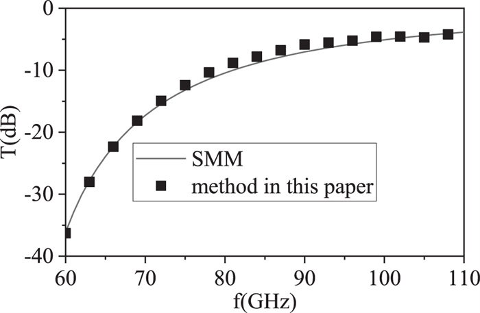
Taking the inhomogeneous plasma slab given in figure 2 as an example, the correctness of the method provided in this paper is numerically verified. The plasma slab is split into 100 sublayers. The collision frequency and the magnetic induction intensity are set to 20 GHz and respectively. As we know, by setting the TC and the half-cone angle to zero, the Bessel vortex beam may degenerate into a plane wave. As a plane wave normally incidence, the variation of power transmission coefficients of the right-handed circularly polarized (RCP) wave with frequency is calculated by both SMM and our method and shown in figure 3. The results indicate that they are in good agreement with each other.
Figure
3.
Variation of the transmission coefficients of the RCP wave with the incident frequency.
In the following subsection, by using the double Gaussian distribution of the plasma density (shown in equation (29)), the effects of parameters of both the multi-layered magnetized plasma slab and the incident beam on the transmitted beams are analyzed numerically in detail. Without specification, the parameters used in equation (29) are the same as those in figure 2.
3.1
Magnitude and OAM mode of the transmitted beams for a Bessel vortex beam incidence
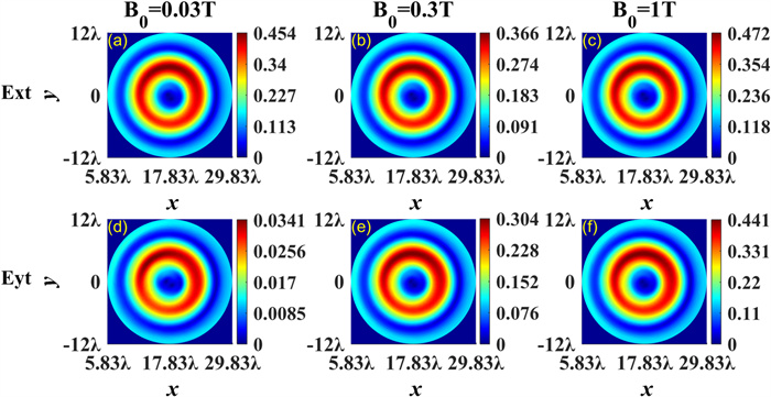
A comparison of the amplitude profiles of the transmitted electric field components and with three different magnetic induction intensities is displayed in figure 4, where Ext and Eyt are corresponding to and respectively. The frequency and the incident angle of the x polarized Bessel vortex beam are 0.1 THz and 30°, respectively. The half cone angle and the TC are set to and The thickness, collision frequency and the number of sublayers of the magnetized plasma slab are the same as those of figure 3.
Figure
4.
Effects of magnetic induction intensity upon the transmitted electric field components and as an x-polarized Bessel vortex beam incidence.
The contours shown in figure 4 indicate that as the magnetic induction intensity increases, so does the magnitude of the component This is because the Faraday rotation angle is proportional to resulting in the gradual transformation of the polarization mode of the beam from x-linear polarization to elliptical polarization. Nevertheless, due to the small impact of the increase of on the permittivity elements and the differences of the eigenvalues among the three cases are small, that is, the deviation of the propagation direction between two characteristic waves in plasma is small, leading to the tiny effect of on the profiles of both and
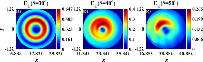
The effects of the incident angle upon the profiles of the total transmitted electric field amplitude () are presented in figure 5. The parameters are the same as those used in figure 4, except The results reveal that with an increase of the magnitude of decreases due to the plasma attenuation, and the center of the transmitted beam is gradually away from the origin of the local coordinate system Moreover, the deviation of the profile of the transmitted electric field from that of the incident field is becoming more and more serious.
Figure
5.
Profiles of the transmitted electric field amplitude with different incident angles.
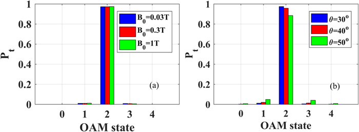
For different applied magnetic fields and incident angle parameters, figure 6 shows the distribution of the OAM spectrum of the transmitted beam. Parameters of both the beam and plasma in figures 6(a) and (b) are the same as those of figures 4 and 5, respectively. The results reveal that B0 does not affect the OAM state distribution, which is in line with that of a homogeneous plasma slab [33]. However, as the incident angle increases, the phase distribution on the wave front of the transmitted beam gradually deviates from that of the incident vortex beam, which reduces the weight of the dominant OAM state.
Figure
6.
Effects of the magnetic induction intensity and the incident angle on OAM spectrum of the transmitted beam, (a) effects of on (b) effects of on
3.2
Effects of the magnetic induction intensity upon the polarization mode of the transmitted beam
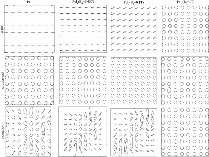
In this section, for the incident beams with different polarization states, the effects of upon the polarization mode of the transmitted beam are simulated numerically. In order to describe the evolution process vividly, figure 7 illustrates the variation of the trajectories of the transmitted electric field vector with The labels on the left side of the diagram x-pol, circular-pol, and radial-pol denote the x-polarization, the circular polarization, and the radial polarization, respectively. The title represents the trajectories of the incident beam, and is corresponding to that of the transmitted beam. The magnitude of magnetic induction intensity follows Except for the incident angle other parameters of both the incident beam and the magnetic plasma slab are the same as those in figure 4.
Figure
7.
Variation of the transmitted electric field vector trajectories with the polarization of the incident beam and the magnetic induction intensity
For an x-polarized incident beam incidence, the vector trajectories are parallel to the x-axis. As the increase of the angle between the trajectory lines and the x-axis increases and gradually evolves to ellipses and further circles. In other words, with an increase of the polarization mode of the transmitted beam changes from linear polarization to elliptical polarization and further to circular polarization. The results are in accord with those shown in figure 3, and can be explained by the Faraday rotation effects of magnetized plasma.
The figure shows that as the incident beam is circular polarization mode, the trajectory lines of the transmitted electric fields are not affected by and still circular. It means that similar to plane waves, no matter what large is, propagation of circularly polarized vortex beam in magnetized plasma will not produce Faraday rotation effect.
When the incident beam turns into radial polarization, its electric field trajectories are either linear or elliptical. After passing through the magnetized plasma slab, with the increase of the electric field trajectory lines of the transmitted field will rotate and change in shape. Furthermore, as the trajectory lines become circular shape, that is, the transmitted beam evolves into circular polarization.
In conclusion, like the plane waves, the linear vortex beam propagating in the magnetized plasma will have the Faraday rotation effect, but the circular polarization will not. With the increase of the polarization of the transmitted beam varies for both x polarization and radial polarization.
3.3
Coaxial incidence of multiple Bessel vortex beams with different TCs
OAM multiplexing in free space communication is widely concerned in wireless optical communication technology, whereas the mode crosstalk of OAM is one of the key points that must be considered and overcome. In this section, for coaxial incidence of multiple Bessel vortex beams with different TCs, using the method mentioned in the above sections, by modifying the expression of the incident beams to
(30)
the magnitude profiles and OAM spectrum characteristics of the transmitted beam can be analyzed. is the number of the Bessel vortex beams, and the subscript denotes the th beam.
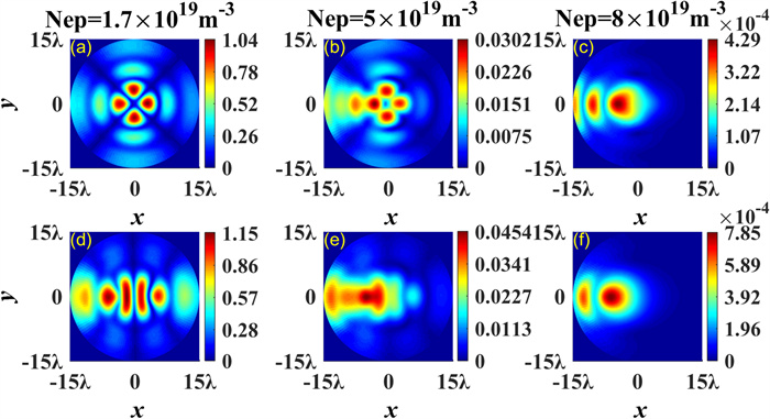
Taking coaxial incidence of several Bessel vortex beams with and as examples, figure 8 presents the variation of magnitude profiles of the transmitted beam with the maximum value of plasma density. The beam parameters are set to and the parameters of the plasma slab are the same as those of figure 2.
Figure
8.
Effects of on magnitude of the transmitted beam for coaxial incident beams, (a)–(c) (d)–(f)
The results shown in figure 8 indicate that the magnitude profile of the total transmitted electric field is closely related to the TC of the superimposed beams and decreases with the increase of Comparing with other regions, distortion in the region () seems more serious. As increases to the amplitude of the total transmitted electric field reduces to This is because the increase of electron density significantly increases the angular plasma frequency, resulting in the serious attenuation of the electromagnetic wave.
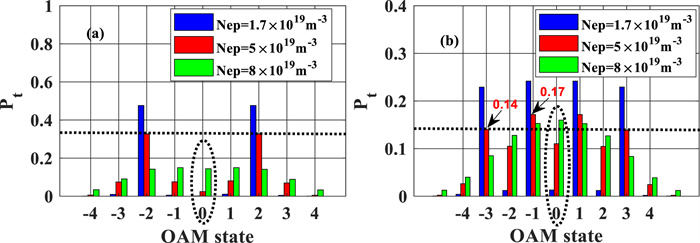
Figure 9 shows the weight distribution of the OAM states of the transmitted beams. Obviously, except the dominant OAM states ( in figure 9(a), in figure 9(b)), some adjacent states are derived, and with the growth of the weight of the dominant OAM state diminishes (which is in accord with the results in [38]). It means that the mutual OAM coupling and crosstalk are very significant. Furthermore, for the cases of and the difference of adjacent TCs of the incident beams plays an important role in the mutual OAM coupling and crosstalk of the transmitted beam, such as the growth of the weight of the OAM state in figures 9(a) and (b). The mechanism of affecting the OAM spectrum distribution is as follows: the increase of the electron density increases the angular plasma density, reduces the real part and increases the imaginary part of the dielectric tensor element of magnetized plasma, changes the wave number of the characteristic waves in the magnetized plasma, and finally affects the spatial distribution of the phase. The phase disturbance can be characterized by the distribution of OAM states.
Figure
9.
OAM state distribution of the transmitted beam for coaxial vortex beams with (a) (b) in different plasma slabs.
A new method to solve the transmission of a THz vortex beam passing through a multi-layered magnetized plasma slab has been provided and extended to the case of multiple coaxial vortex beams incidence. By analyzing the transmission of single and multiple x-polarized Bessel vortex beams through an inhomogeneous magnetized plasma slab with double Gaussian distribution, the major conclusions are obtained as follows. (1) The propagation of a linear polarized vortex beam in magnetized plasma had similar Faraday rotation effects to that of plane waves. With the increase of the magnitude of increased, and the trajectories of the transmitted electric field vector gradually evolved to circular. (2) Owing to the tiny impact of the increase of on the permittivity tensor, the phase disturbance caused by the variation of was weak, so that the distribution of OAM state had not changed. (3) The increase of the incident angle made the plasma attenuation increase, and the phase distribution of the wavefront was seriously deviated from the incident beam, therefore, the contours and the OAM state of the transmitted beam were distorted dramatically. (4) The increase of the maximum value of the plasma density distorted the profiles of the transmitted field and the distribution of the OAM state severely. On average, the conclusions of the above-mentioned analysis are helpful to qualitatively evaluate the influence of plasma parameters on communication quality, and have theoretical reference value for selecting appropriate beam parameters in THz OAM communication. Meanwhile, it is noteworthy that the method provided in this paper can spread to study the propagation characteristics of other shaped beams in magnetized plasma.
Appendix
The coefficient matrices in equations (22)–(24) are
(A1)
(A2)
(A3)
where and are presented in equation (12).
Acknowledgments
This work was supported by National Natural Science Foundation of China (Nos. 62171355, 61801349, and 61875156), the Natural Science Basic Research Plan in Shaanxi Province of China (No. 2020JM-192), the Stable Support Project of Basic Scientific Research Institutes (Nos. A131901W14, A132001W12), the Science and Technology Foundation of State Key Laboratory of Electromagnetic Environment, and the 111 Project (No. B17035).
Zhao Z et al 2020 Fundamental system-degrading effects in THz communications using multiple OAM beams with turbulence Proc. of 2020 IEEE Int. Conf. on Communications (ICC)(Dublin, Ireland 2020)(IEEE) p 1

 DownLoad: