Demai ZENG, Hong LI, Jinwen LIU, Yongjie DING, Liqiu WEI, Daren YU, Wei MAO. Numerical study of the effect of aft-loaded magnetic field on multiple ionizations in Hall thruster[J]. Plasma Science and Technology, 2022, 24(7): 074005. DOI: 10.1088/2058-6272/ac5788
Citation:
Demai ZENG, Hong LI, Jinwen LIU, Yongjie DING, Liqiu WEI, Daren YU, Wei MAO. Numerical study of the effect of aft-loaded magnetic field on multiple ionizations in Hall thruster[J]. Plasma Science and Technology, 2022, 24(7): 074005. DOI: 10.1088/2058-6272/ac5788
Demai ZENG, Hong LI, Jinwen LIU, Yongjie DING, Liqiu WEI, Daren YU, Wei MAO. Numerical study of the effect of aft-loaded magnetic field on multiple ionizations in Hall thruster[J]. Plasma Science and Technology, 2022, 24(7): 074005. DOI: 10.1088/2058-6272/ac5788
Citation:
Demai ZENG, Hong LI, Jinwen LIU, Yongjie DING, Liqiu WEI, Daren YU, Wei MAO. Numerical study of the effect of aft-loaded magnetic field on multiple ionizations in Hall thruster[J]. Plasma Science and Technology, 2022, 24(7): 074005. DOI: 10.1088/2058-6272/ac5788
It is assumed that the shift of a strong magnetic field region with a positive gradient from exit plane to outside, namely the transit from a normal loaded magnetic field to an aft-loaded one, enhances the multiple ionization process in the magnetically shielded Hall thruster. To confirm this conjecture, a comparative study is carried out numerically with a particle-in-cell method. The simulation results prove that compared with the normal loaded magnetic field, the application of aft-loaded magnetic field enhances the multiple ionization process. This study further analyzes the ionization characteristics of the transition from low-charged ions to high-charged ions under two magnetic field conditions and the influence of the magnetic strength of aft-loaded magnetic field on the multiple ionization characteristics. The study described herein is useful for understanding the discharge characteristics of Hall thruster with an aft-loaded magnetic field.
A Hall thruster is a type of power device used in the field of electric propulsion, and its main principle is to ionize and accelerate the propellant gas (Xenon in general) using electric and magnetic fields and to generate thrust [1, 2]. Hall thrusters have the advantage of being highly efficient, of having highly specific impulses and a simple structure. In addition, with the rapid development of the commercial aerospace industry, Hall thrusters will become more widely used in aerospace fields such as the propulsion of small or microsatellites [3, 4].
Hall thruster consists of a discharge channel, anode, magnetic circuit, and cathode. The magnetic field in the Hall thruster is formed by the magnetic circuit, mainly in the radial direction, and the electrons are magnetized, whereas the ions are not. Electrons are emitted from the cathode, they enter the channel, and are captured by the magnetic field. The neutral gas diffuses from the anode to the downstream of the channel. Ions are generated by the ionization collisions between atoms and electrons, and then accelerated by the self-consistent electric field to form thrust.
A multiple ionization effect exists in the working process of a Hall thruster, although the ionization of the propellant gas is dominated by a single ionization [5, 6]. Meanwhile, the multiple ionization process is closely related to the discharge condition of the thruster, such as discharge voltage, propellant flow rate, magnetic field configuration, and the amount of vacuum [6–10]. The geometry of the thruster also affects the characteristics of multiple ionization [11, 12]. The characteristics of multiple ionization affect erosion of the discharge chamber and efficiency, therefore it is worthy of further study [9, 11, 12].
The magnetically shielded Hall thruster has a significant advantage in extending the service life of a Hall thruster, therefore this technique is widely used [13–16]. Hofer et al used an E × B probe to measure the proportion of multiple charged ions on two 6 kW thrusters, one provided with magnetic shielding technology and the other without such technology, and found that the application of magnetic shielding significantly enhances the multiple ionization process [17]. The main differences between magnetically shielded thrusters and unshielded thrusters in design include, the position of the strong magnetic field region with a positive gradient, the curvature of the magnetic field line near the wall area, and the shape of the discharge channel [18, 19]. For unshielded thrusters, the magnetic field with a positive gradient is fully located inside the channel, which is a normal loading manner. For magnetically shielded thrusters, part of the magnetic field with a positive gradient is located outside the channel; specifically, the magnetic field peak is shifted from the exit plane to outside. Therefore, it can be called the aft-loading of the magnetic field [20]. The experiment confirmed that the ionization zone and acceleration zone move downstream in the magnetically shielded thrusters [18]. As a result, part or all of the acceleration zone is located outside the channel. The majority of the potential drop is located downstream from the exit of the channel, which in turn causes great changes in the electron energy conversion process [18]. Thus, it is guessed that the transit from a normally loaded magnetic field to an aft-loaded one [20] is the main reason for the enhancement of multiple ionizations in the magnetically shielded Hall thruster. The physical mechanism of it has yet to be clearly explained. Based on this, a numerical simulation is used to compare and analyze the mechanisms of the influence of the two different loading manners of magnetic field on the multiple ionization process, and thereby help to understand the characteristics of the multiple ionization process of a Hall thruster with aft-loaded magnetic field.
The remainder of this paper is arranged as follows. Section 2 introduces the numerical model and research methods applied. Section 3 describes and analyzes the simulation results. Section 4 provides some concluding remarks.
2.
Research methods
Particle-in-cell (PIC) simulation is a powerful method to study the physical processes of Hall thrusters [21–24]. Because a Hall thruster has an axisymmetric cylindrical structure, its discharge can be considered uniform along the azimuthal direction. Therefore, only the axial (z) and radial (r) directions are considered when constructing the calculation model. Our team has developed a mature PIC platform with a 2D3V framework, which has been used to solve many physical problems. A brief introduction of the PIC model is presented below. The details can be found in [25–30]. To investigate the topic of this study, the PIC platform is updated by considering the multiple ionization process.
2.1
PIC numerical model
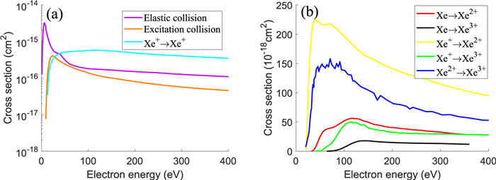
In the previous model, only elastic collision, excitation collision and single ionization collisions between atoms and electrons were considered. In order to study the multiple ionization, a total of eight types of independent collisions between electrons and atoms or ions are considered, where the electron is the incident particle, including an elastic collision, excitation collision, and six types of ionization collisions, namely, Xe→Xe+, Xe→Xe2+, Xe→Xe3+, Xe+→Xe2+, Xe+→Xe3+, Xe2+→Xe3+. In addition, the movement of high-charged ions is also considered. The collision cross-section data of elastic collision, excitation collision and single ionization are the same as those used by Szabo [31] and shown in figure 1(a). The collision cross-section data of multiple ionization collisions are summarized in [32–38] and shown in figure 1(b). The calculation process of an electron collision is optimized using the Monte Carlo Collison (MCC) method and the NULL-collision method proposed by Vahedi [39]. After electrons collide, the collision form can be determined through a single estimate. In addition, a Bohm anomalous conduction is also considered in the model [40] and the Bohm collision frequency νB is used to equal this effect:
where CB is the semi-empirical coefficient, e is the basic charge quantity, B is the strength of the magnetic field, and me is the electron mass. Coulomb and charge exchange collisions have yet to be considered.
The induced magnetic field is ignored in the model since its magnitude is much smaller than that of the applied one. Therefore, only the electrostatic model is considered, and the Poisson equation is adopted and numerically solved to obtain the electric field.
For particle dynamics, the motion of the atoms is processed according to the free molecular flow; the motion of electrons is controlled by an electric and magnetic field; the motion of ions is only influenced by the electric field.
Five typical boundary conditions are considered, as shown in figure 2. On the boundary of the anode, the neutral atoms are injected and the potential is set as the discharge voltage. Generally, the material of the discharge channel is BN ceramic. Therefore, the channel wall is regarded as a dielectric boundary. On the boundary of the dielectric wall, a normal electric field is determined by the charge density deposited on the wall. In addition, the secondary electron emission (SEE) effect of an electron-wall collision is considered in the model [41, 42]. The face of the pole boundary is considered a capacitance boundary, and its potential is determined by the amount of charge deposited on the surface. On the open boundary, electrical neutrality is maintained by injecting electrons, and the potential is set to zero. Moreover, on the symmetry boundary, the radial electric field is set to zero and the particles are specularly reflected.
2.2
Magnetic field intensity distribution for different loading manners
In this study, a simulated thruster with a size similar to those of SPT-100 and PPS-1350 [43] with a power of 1.35 kW was selected, as shown in figure 2. The magnetic field used in the PIC simulation is calculated using the open-source software named Finite Element Method Magnetics (FEMM). According to the research purpose, two magnetic field configurations, aft-loaded magnetic field and normal loaded magnetic field were designed, as shown in figure 3. For the aft-loaded magnetic field, the position of the maximum magnetic field strength realized along the centerline is pushed from the channel exit to a site 4 mm outside the channel. The magnetic field strength at the channel exit on the channel centerline accounts for 86% of the maximum magnetic field, and this ratio in the 6 kW power magnetic-shielding Hall thruster developed by Jet Propulsion Laboratory (JPL) is 83% [13, 14, 19]. Thus, they are similar in magnetic field intensity distribution, which satisfies the characteristics of the aft-loaded magnetic field.
Figure
3.
Distribution of normalized magnetic field strength along the channel centerline for different magnetic field configurations.
In the simulation, the discharge voltage is set as 300 V and the anode mass flow rate is set as 5.65 mg s-1. Regarding the Bohm coefficient CB in the semi-empirical formula, it was found that the CB value outside the channel is larger than that inside the channel [40, 44]. Considering that part of the positive-gradient region of the aft-loaded magnetic field is located outside the channel, different Bohm coefficients are used depending on the gradient of the magnetic field [45]. CB is selected as 1/310 for the positive-gradient region and 1/18 for the negative-gradient region. These Bohm coefficients are chosen to ensure that the simulated performance is closer to the experimental one [44, 46, 47].
3.1
The influence of the loading manner of the magnetic field on the ionization process
In order to compare the proportions of differently charged ions in the discharge process, the ion current ratio and ion quantity ratio need to define respectively. It is shown in formulas (2)–(4), where Iia is ion current formed by Xea+, Iitotal is sum of Iia, Rcurrenta is ion current ratio for Xea+, and Rquantitya is ion quantity ratio for Xea+. a represents the charge state of the Xe ion.
Itotal i=3∑a=1Iai
(2)
Racurrent =IaiItotal i×100%(a=1,2,3)
(3)
Raquantity =Iai/a∑(Iai/a)×100%(a=1,2,3)
(4)
Table 1 shows the different charged ion currents and their proportions of the total currents under different magnetic field loading manners. It can be seen that the change in loading manner of magnetic field from normal loading to aft-loading enhances the multiple ionization effect, where the proportion of Xe2+ and Xe3+ increases.
Table
1.
Multiple charged ion currents and ratios under different magnetic field loading manners.
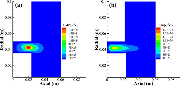
To further analyze the influence of the magnetic field loading manner on the ionization process, the contour of the ionization collision rate distribution of the particle collisions is given. It should be noted that, according to the introduction to the PIC numerical model in section 2.1, six types of ionization collision processes were considered in this study. Undoubtedly, the process of Xe→Xe+ plays a leading role, and the Xe→Xe+ ionization collision rate distributions are shown in figure 4. The proportion of Xe2+ in the product is second only to Xe+, therefore, the following content will mainly focus on the generation of Xe2+. The generation of Xe2+ comes from Xe+→Xe2+ and Xe→Xe2+, and their ionization collision rate distributions are shown in figures 5 and 6.
Figure
4.
Contours of Xe→Xe+ ionization rate of (a) aft-loading case and (b) normal loading case.
First, from the perspective of the ionization rate, the ionization rate of the Xe→Xe+ ionization process corresponding to the normal loaded magnetic field is higher, and the ionization rates of Xe→Xe2+ and Xe+→Xe2+ corresponding to the aft-loaded magnetic field are both higher. The ionization rate represents the probability of occurring of multiple ionization. This is consistent with the conclusion that the aft-loading of the magnetic field enhances the multiple ionization process. In addition, the results in figures 5 and 6 can illustrate that there are two ways to generate Xe2+ in both cases, namely Xe→Xe2+ and Xe+→Xe2+, and between the two, Xe+→Xe2+ is dominant. Similarly, by using the PIC for a calculation and comparison, it can be seen that Xe+→Xe3+ is dominant among the three ionization processes generated for Xe3+, namely, Xe→Xe3+, Xe+→Xe3+, and Xe2+→Xe3+. So it can be inferred multiply charged ions are more likely created from singly charged ions than directly from neutrals.
Second, two characteristics of the multiple ionization process can be concluded from the contour of the ionization rate distribution. On one hand, compared to the normal loading case, in the aft-loading case, multiple ionization collisions occur at the position closer to the channel downstream. On the other hand, for the generation of Xe2+, in both cases, compared to the ionization process of Xe→Xe2+, the ionization process of Xe+→Xe2+ occurs on closer to the channel downstream.
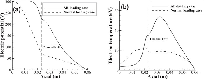
In a Hall thruster, the ionization rate Rion of the propellant is shown in formula (5), where ne is the electron density, na is the atom density, and βi is the ionization rate coefficient. Since ionization rate coefficient and electron temperature are directly related, the atom density and electron temperature are the main factors determining the magnitude of the ionization rate. The distributions of electric potential and electron temperature on the channel centerline are shown in figure 7.
Rion =nenaβi
(5)
Figure
7.
Distribution of (a) electric potential and (b) electron temperature on the channel centerline.
In addition, the magnetic field strength is one of the key factors that determine the spatial conductivity of electrons, so the magnetic field strength and its distribution are the key factors that determine spatial conductivity. Combining figures 3 and 7, compared to normal loading, aft-loading of magnetic field makes the positive-gradient magnetic field partly located outside the channel, causing significant changes in the conductivity inside and outside the channel. In the aft-loading, the conductivity inside the channel increases, and the potential drop in the channel decreases.
In the aft-loading case, the main potential drop is located outside the discharge channel, reaching 240 V on the channel centerline. In addition, the electrons emitted from the cathode rapidly reach a high electron temperature with a peak value of 54 eV under the strong heating of the electric field outside the channel. Such a high electron temperature enhances the ionization collision effect outside the channel, although compared to that inside the channel, the density of heavy particles outside the channel remains low, and thus the electrons are still at a high temperature of 32 eV when reaching the channel exit.
In the normal loading case, the main potential drop is located inside the channel, reaching 80 V on the channel centerline, and thus the heating effect of the electric field outside the channel on the electrons is poor, and the peak temperature of the electrons outside the channel is only 19 eV. As the electrons move toward the channel exit, the ionization energy loss is slightly higher than the heating effect of the electric field, and the temperature of the electrons at the channel exit is 18 eV.
Combining figures 4 and 5, when an electron emitted from the cathode moves toward the near-exit, it first encounters a large number of propellant atoms, and when propellant is freely diffused from the anode into the channel downstream, the gas becomes evenly dispersed within the entire channel between the inner and outer walls, and the gas density along the centerline experiences a significant drop from upstream to downstream. In aft-loading case, the temperature of the electron entering the channel is 32 eV. Such a high electron temperature causes an immediately strong ionization collision between the atom and electron. Considering figure 1, the probability of occurrence of a multiple ionization collision is high. In a normal loading case, the electrons entering the channel are at a low electron temperature of 18 eV. According to formula (4), such a propellant density and electron temperature environment fails to meet the condition of a large number of ionizations. Therefore, the electron continues to move upstream under the heating effect of the electric field within the channel, although because the wall surface energy loss of the electron in the channel is also large, the electron temperature is basically maintained at 20 eV, which is much lower than the electron temperature of 32 eV at the channel exit in aft-loading case. However, as the electron moves closer to the anode, the atom density of the propellant increases significantly. According to formula (4), there will be numerous ionization collisions between the electrons and atoms, causing an avalanche effect, and thus ionization is completed. Compared to the aft-loading case, the rate of double and even higher ionization collisions is low owing to the low electron temperature, and as the ionization area is closer to the anode, the propellant is distributed more intensively and the density becomes higher; thus, the rate of single ionization collisions increases.
Combining figures 3 and 6, the aft-loading of the magnetic field leads to the zone of ionization process of Xe→Xe+ to move downstream, and the generation of Xe2+ is mainly through process of Xe+→Xe2+. According to formula (4), the zone of ionization process of Xe+→Xe2+ must be downstream of the zone of ionization process of Xe→Xe+. Therefore, the zones of ionization process of Xe+→Xe2+ and Xe→Xe+ both move downstream. Compared to the normal loading case, in the aft-loading case, the main potential drop is outside the channel, where interaction between the channel and the electron is lost, the electron temperature is higher at the channel exit. The distance between the Xe→Xe+ ionization process zone and the exit of the channel is reduced, which leads to the weakening of the cooling effect of the channel and heavy particles on the electrons. Finally, electrons in the zone of ionization process of Xe+→Xe2+ have higher energy, therefore, the generation of Xe2+ is enhanced.
3.2
The influence of magnetic field strength on the ionization process in aft-loading case
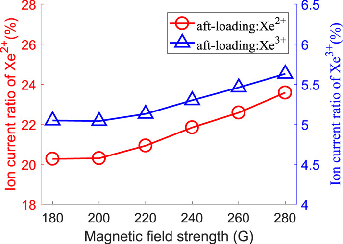
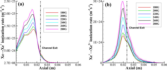
In section 3.1, the multiple ionization process was simulated under different magnetic field distributions but the same maximum magnetic field strength at the centerline of the channel. The change of the multiple ionization in different loading manners is due to the relative change of the spatial conductivity, and the conductivity is greatly affected by the strength of the magnetic field. Therefore, the influence of magnetic field strength on ionization process in aft-loading case needs to be considered. This part focuses on the influence of magnetic field strength on the ionization process in aft-loading case, because the strength and configuration of the magnetic field are both key factors for the ionization process. Based on previous experimental experience, the range of maximum magnetic field intensity of the channel centerline has been selected. The range of variation of the maximum magnetic field is 180–280 G under the conditions of the aft-loaded magnetic field. The simulation result is shown in figure 8. The proportion of Xe2+ and Xe3+ increases with the increase in magnetic field strength under the aft-loaded magnetic field.
Figure
8.
Multiple charged ion currents ratio with different magnetic field strengths in the aft-loading case.
This part still uses Xe2+ as the research object. It was pointed out in section 3.1 that the Xe+→Xe2+ ionization process is dominant in the ionization process with the generation of Xe2+, and thus the Xe+ density is a key factor determining the ionization rate of the Xe+→Xe2+ process.
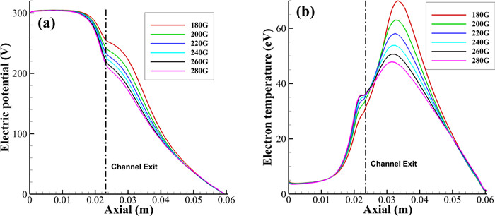
In the positive gradient region of the magnetic field, the plasma instability is suppressed and the classical conduction is dominant; the electron conductivity is thus inversely proportional to the square of the magnetic field strength. The Bohm conduction is dominant in the negative gradient region of the magnetic field, where the electron conductivity is inversely proportional to the magnetic field strength. Therefore, in the aft-loading case, with the increase of the magnetic field strength, the ratio of the conductivity outside the channel to the inside of the channel increases, and the potential drop outside the channel decreases, as shown in figure 9(a). The value of electron temperature is the result of electric field heating and collision cooling. When the electron gains higher energy in the acceleration zone, the collision loss energy increases, and the electron temperature decreases in the ionization zone, as shown in figure 9(b). The production rate of Xe2+ is mainly determined by processes of Xe→Xe+ and Xe+→Xe2+, in which the electron temperature is the key factor. So higher electron temperature in the ionization zone is the main reason for the increase in production rate, as shown in figures 10(a) and (b). The results show that the proportion of Xe2+ increases as the magnetic field strength increases.
Figure
9.
Distributions of (a) electric potential and (b) electron temperature on the channel centerline in the aft-loading case.
The variance of the proportion of Xe3+ with magnetic field strength has the same trend as that of Xe2+. It can be well-understood since both of them are generated mainly from the ionization of Xe+.
4.
Conclusions
In this work, the mechanisms of the influence of two different loading manners of a magnetic field, normal loading and aft-loading, on the multiple ionization process of a Hall thruster were studied using a particle-in-cell simulation method. The simulation results proved the assumption that the shift of the strong magnetic field region with a positive gradient from the exit plane to outside indeed enhances the multiple ionization process. The increase of electron temperature in the ionization region is the main reason for the enhancement of multiple ionization. Compared with normal loading, in the aft-loading case, the position of the ionization zone moves downstream of the channel, resulting in the weakening of the cooling effect of the channel and the increase of the electron temperature. The increase of the magnetic field strength changes the relative conductivity of the ionization zone, reduces the collision loss in the acceleration zone, and leads to the increase of the electron temperature.
Acknowledgments
This work is funded by National Natural Science Foundation of China (Nos. 52076054 and 51736003), Advanced Space Propulsion Laboratory of Beijing Institute of Control Engineering and Beijing Engineering Research Center of Efficient and Green Aerospace Propulsion Technology (No. LabASP2019-04), the Civil Aerospace Technology Pre-research Project (No. D03015) and the Defense Industrial Technology Development Program (No. JCKY2019603B005).
King L B and Gallimore A D 2000 J. Propul. Power16 1086 doi: 10.2514/2.5681
[6]
Kim S W and Gallimore A D 2002 J. Spacecr. Rock.39 904 doi: 10.2514/2.3897
[7]
Huang W S, Kamhawi H and Haag T 2013 Effect of background pressure on the performance and plume of the hivhac hall thruster 33rd Int. Electric Propulsion Conf. (Washington, USA) (IEPC)
[8]
Reid B et al 2008 Angularly-resolved ExB Probe spectra in the plume of a 6-kW hall thruster 44th AIAA/ASME/SAE/ASEE Joint Propulsion Conf. & Exhibit (Hartford, USA) (AIAA)
[9]
Hofer R R and Gallimore A D 2004 Efficiency analysis of a high-specific impulse Hall thruster 40th AIAA/ASME/SAE/ASEE Joint Propulsion Conf. and Exhibit (Fort Lauderdale, USA) (AIAA)
Diamant K et al 2008 Low power cylindrical Hall thruster performance and plume properties 44th AIAA/ASME/SAE/ASEE Joint Propulsion Conf. & Exhibit (Hartford, USA) (AIAA)
[13]
Shastry R, Gallimore A D and Hofer R R 2011 Experimental characterization of the near-wall plasma in a 6-kW Hall thruster and comparison to simulation 47th AIAA/ASME/SAE/ASEE Joint Propulsion Conf. & Exhibit (San Diego, California, USA) (AIAA)
[14]
Mikellides I G 2013 The effectiveness of magnetic shielding in high-Isp Hall thrusters 49th AIAA/ASME/SAE/ASEE Joint Propulsion Conf. (San Jose, CA, USA) (AIAA)
[15]
Mikellides I G et al 2011 Phys. Plasmas18 033501 doi: 10.1063/1.3551583
[16]
Jorns B A and Hofer R R 2014 Phys. Plasmas21 053512 doi: 10.1063/1.4879819
[17]
Hofer R R et al 2012 Design of a laboratory Hall thruster with magnetically shielded channel walls, phase Ⅱ: Experiments 48th AIAA/ASME/SAE/ASEE Joint Propulsion Conf. & Exhibit (Atlanta, Georgia, USA) (AIAA)
[18]
Mikellides I G et al 2014 J. Appl. Phys.115 043303 doi: 10.1063/1.4862313
[19]
Hofer R R 2013 Magnetically-conformed, variable area discharge chamber for Hall thruster, and method US Patent 8407979
Vial V et al 2011 PPS 1350-G performance assessment with permanent magnets 32nd Int. Electric Propulsion Conf. (Wiesbaden, Germany)
[44]
Mikellides I G et al 2016 Hall2De simulations with a first-principles electron transport model based on the electron cyclotron drift instability 52nd AIAA/SAE/ASEE Joint Propulsion Conf. (Salt Lake City, UT) (AIAA)
[45]
Morozov A I et al 1972 Sov. Phys. Tech. Phys.17 482
Zeng, D., Li, H., Lian, H. et al. Influence of internally mounted cathode location on discharge characteristics of Hall thrusters. Vacuum, 2025.
DOI:10.1016/j.vacuum.2025.114019
2.
Ma, H., Li, J., Li, J. et al. Effect of pulse frequency on discharge characteristics of Hall thruster under pulsating operation. Vacuum, 2024.
DOI:10.1016/j.vacuum.2024.113106
3.
Ma, D., Yu, Q., Liu, X. et al. Magnetic focusing of low-power Hall thruster with a center-mounted hollow cathode. Vacuum, 2023.
DOI:10.1016/j.vacuum.2023.112650
4.
Ma, H., Zhou, L., Wang, Z. et al. Plasma dynamics of Hall thrusters under pulsating operation. Vacuum, 2023.
DOI:10.1016/j.vacuum.2023.112532
5.
Zeng, D., Li, H., Liu, J. et al. Optimization of a Long-Lifetime Hall Thruster with an Internally Mounted Cathode. AIAA Journal, 2023, 61(10): 4259-4266.
DOI:10.2514/1.J062246

 DownLoad: