Figure
1.
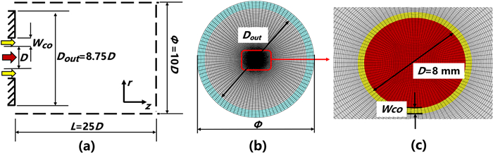
Schematic diagram of the physical model and computational domain.
| Citation: |
Xu ZHOU, Xianhui CHEN, Taohong YE, Minming ZHU, Weidong XIA. Numerical study of the effect of coflow argon jet on a laminar argon thermal plasma jet[J]. Plasma Science and Technology, 2022, 24(5): 055409. DOI: 10.1088/2058-6272/ac52eb

|
The effects of the velocity and width in coflow argon jet inlet on the flow characteristics of laminar argon thermal plasma jet flowing into the cold air have been studied by the large eddy simulation methods. The Kelvin–Helmholtz instability between argon thermal plasma jet and coflow argon jet causes the transition from a laminar jet to a turbulent jet in the presence of coflow argon jet. Moreover, increasing the velocity and width in coflow argon jet inlet can enhance turbulent transport and provoke coherent structure in the downstream of thermal plasma jet. And the mixing characteristics between argon thermal plasma, coflow argon and ambient air are strengthened. In addition, the width in coflow argon jet inlet has a significant effect on the distribution of temperature in the upstream of thermal plasma jet. It was also found that the transition occurs in advance with the increase of velocity and width in coflow argon jet inlet.
The various flow configurations of thermal plasma, including free jets [1–3], coflow jets, transverse jets [4–6] and counter flows [7–9], etc, have been widely used in industrial applications. As one of the basic flow configurations, thermal plasma jets integrated with coflow argon jets have been widely used in welding, cutting, spraying and material preparation, and so on.
In atmosphere plasma spraying, solid particles are heated and melted by the thermal plasma jets with sufficiently high temperature and velocity, which then splash on the substrate in order to form the coatings with special physical and chemical properties [10]. However, the thermal plasma jets will be rapidly decelerated and quenched due to the large amount of entrained cold ambient air into jets, which seriously affects the properties of the coatings, such as porosity, thickness and oxide contents, and even leads to the failure of coatings [11–14]. Generally, coflow argon jets are adopted at the end of the nozzle of the plasma torch to decrease the entrainment of cold air into thermal plasma jets. Furthermore, coflow argon contributes to creating an inert gas atmosphere, and avoids the interaction between solid particles with high temperature and ambient air [15–21].
In the process of thermal plasma arc welding and cutting, coflow argon jets cannot only inhibit the air oxidation of materials, but also protect the nozzle of the thermal plasma torch from molten materials splashed from the work-piece. Coflow argon jets also provide a cold boundary layer around the anode wall, which reduces the heat carried away by cooling water. In addition, coflow argon jets squeeze the arc column and raise the core temperature of thermal plasma jet, which contribute to improving the power density of thermal plasma [22–24].
Recently, thermal plasma jets integrated with coflow argon jets have shown a unique advantage of superfast production graphene [25]. The graphene prepared by this method shows few basal defect and presents high quality. The entire exfoliation process includes three parts: thermal shock of graphite from thermal plasma, and two-stage shearing in the laminar and turbulent region of thermal plasma jets. The experimental results also show that the flow rate of coflow argon jets have a significant influence on the temperature, velocity and exfoliation efficiency of graphite.
Many experimental and numerical studies of the momentum, mass and heat transfer characteristics of thermal plasma free jets have been implemented [1–3, 26–29]. Although thermal plasma jets integrated with coflow argon jets have been widely used in industrial applications, the interactions between coflow argon jets and thermal plasma jets are unclear. Kim et al [17] found that the coflow argon jets with high velocity are conducive to obtaining a thick coating with low porosity and oxide contents. Experimental studies were carried out to investigate the effects of different coflow nozzle configurations on the electro-thermal efficiency of plasma torch [18]. A small number of numerical simulations were performed to investigate the effect of coflow argon jets on the content of cold air into thermal plasma jets. Two-dimensional numerical simulation results show that coflow argon jets can effectively reduce air entrainment into the turbulent plasma jets, but have no significant influence on the distribution of temperature and velocity in the thermal plasma jets [16]. Cheng et al [19] found that the velocity and width in coflow argon jet inlet have significant impacts on the ambient air content in the laminar thermal plasma jets.
Most of experiment studies focused on the properties of materials obtained by the thermal plasma jets integrated with coflow argon jets. However, the flow characteristics of laminar thermal plasma jets integrated with coflow argon jets are unclear due to the limitation of experimental diagnostic methods, and the properties of materials are closely related to the flow characteristics of thermal plasma jets. On the other hand, numerical studies have been used to reveal the flow mechanisms of thermal plasma jets due to the improvement of computational performance. The steady-state assumptions, two-dimensional axisymmetric computational domain, and standard
As shown in figure 1, the diameter of thermal plasma jet inlet (marked in red in figure 1) is D=8 mm. The coflow argon jet inlet (marked in yellow in figure 1) is adjacent to the thermal plasma jet inlet, and the width in coflow argon jet inlet
In this paper, the laminar argon thermal plasma jet flowing into the ambient air is used as a base case 1. Table 1 shows the detailed parameters of laminar thermal plasma jet. The maximum velocity
| Base case 1 | 600 | 13 000 |
 DownLoad:
CSV
DownLoad:
CSV
| Case | ||
| Case 2 | 20 | 0.5 |
| Case 3 | 50 | 0.5 |
| Case 4 | 20 | 1.16 |
DownLoad:
CSV
In our previous work [37], the numerical codes have been embedded and validated to solve argon thermal plasma jet flowing into the cold argon based on the OpenFOAM [36]. The following assumptions are made: (ⅰ) the plasma is in the LTE (Local Thermodynamic Equilibrium) and LCE (Local Chemical Equilibrium) state; (ⅱ) the plasma is assumed to be optically thin, so the radiative heat loss is modeled as a source term dependent on the component and temperature of plasma; and (ⅲ) the buoyancy effects are negligible because of their smallness. Based on the foregoing assumptions, the filtered large eddy simulation compressible governing equations are
| ∂ˉρ∂t+∂ˉρ˜ui∂xi=0 | (1) |
| ∂ˉρ˜uj∂t+∂ˉρ˜ui˜uj∂xi=-∂ˉp∂xj+∂∂xi(ˉτij-τSGSij) | (2) |
| ∂ˉρ˜h∂t+∂ˉρ˜ui˜h∂xi=∂∂xi(kcp∂˜h∂xi-τSGS˜h)-ˉQ |
| -∂∂xi[(hA-hB)((μSc∂˜YA∂xi-τSGS˜YA)+kcp∂˜YA∂xi)] | (3) |
| ∂ˉρ˜YA∂t+∂ˉρ˜ui˜YA∂xi=∂∂xi(μSc∂˜YA∂xi-τSGS˜YA), | (4) |
where, superscript '~' represents Favre-filtered operation, and '–' represents spatially-filtered operation for large eddy simulation.
| ˉτij=2μˉSij-23μˉSkkδij, | (5) |
where,
In the governing equations (2)–(4), the sub-grid scale terms denoted by superscript 'SGS' are closed by the Smagorinsky model [39]. The sub-grid stress term
| τSGSij=ˉρ˜uiuj-ˉρ˜ui˜uj=-2ˉρvt(ˉSij-13ˉSkkδij)+23ˉρδijkSGS, | (6) |
where, the sub-grid viscosity is solved by
| τSGS˜h=ˉρ˜uih-ˉρ˜ui˜h=-ˉρνtPrt∇˜h | (7) |
| τSGS˜YA=ˉρ˜uiYA-ˉρ˜ui˜YA=-ˉρνtSct∇˜YA, | (8) |
where, the turbulent Prandtl number
| ∂ˉρ˜φ∂t+∂ˉρ˜ui˜φ∂xi=∂∂xi(μSc∂˜φ∂xi-τSGS˜φ), | (9) |
where, the sub-grid scalar flux term
Figure 1 shows the computational domain and grid employed in the simulations. Computing domains are 25D×5D×2π in size and divided into 350×99×96 hexahedral structured grids. The total number of hexahedral grids are about 3.5 million. Moreover, the minimum grids can be found in the jet inlet and shear layer, and the size is 0.08 mm.
Table 3 shows the boundary conditions employed in this study. The inflow conditions of velocity and temperature in the argon thermal plasma jet inlet satisfy the following distributions [1, 3, 27]
| U=Uj[1-(rRin)nU] | (10) |
| T=(Tj-Tw)[1-(rRin)nT]+Tw, | (11) |
| Boundary | p | T | |||
| Thermal plasma jet inlet | Equation (10) | Equation (11) | |||
| Coflow argon jet inlet | Equation (12) | ||||
| Wall | |||||
| Other boundaries | p = 1 atm |
DownLoad:
CSV
where, the jet radius is
| U=1.218Uco(1-2δ1.01Wco)1/7, | (12) |
where,
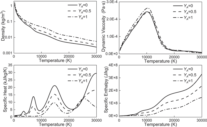
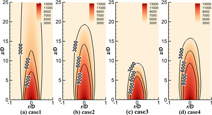
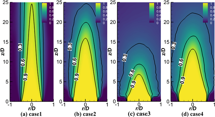
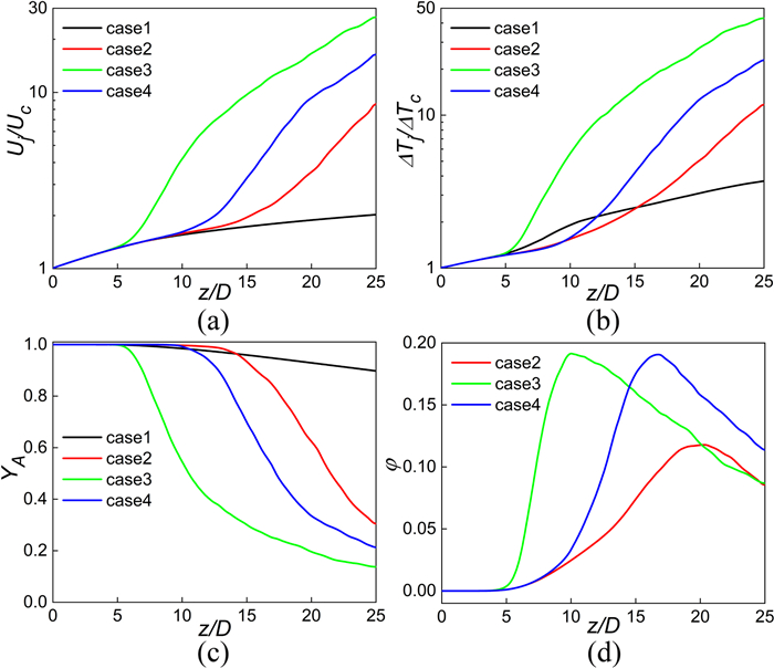
Figures 3–6 show the spatial distributions of mean axial velocity, mean temperature, mean argon thermal plasma mass fraction and mean passive scalar for cases 1–4. It can be seen that the effects of velocity and width in the coflow argon jet inlet on the mean flow field are obvious in comparison to base case 1. With increasing velocity and width in the coflow argon jet inlet, the length of argon thermal plasma jet or high temperature region reduces gradually, and the gradient of velocity and temperature enhance obviously. The thermal plasma jet has changed from a long laminar jet dominated by the molecular transport mechanism to a turbulent jet dominated by the turbulent transport mechanism, and the entrainment rate of the coflow argon and ambient air into the thermal plasma jet is significantly improved. For the case 3 and case 4 with the same mass flow in the coflow argon jet inlet, the effect of increasing velocity of coflow argon jet inlet on the mean flow field is far greater than that of increasing width of coflow argon jet inlet. It is worth noting that the lengths of regions in which the temperature surpasses 6000 K in case 2 and case 4 are slightly longer than those of case 1. Obviously, more coflow argon rather than cold air is entrained into upstream of thermal plasma jet due to the presence of coflow argon jet. On the other hand, the specific enthalpy and specific heat of argon are much lower than those of air at the same temperature, which causes the higher temperature in the upstream of the case 2 and case 4.
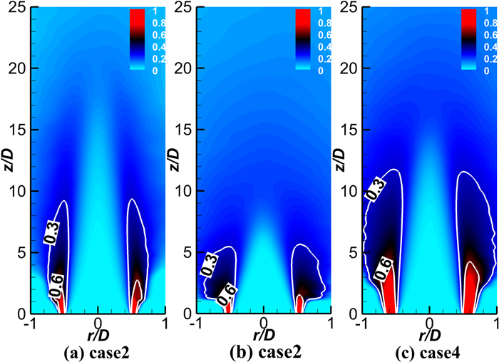
Although the mean argon mass fraction decays faster in the axial direction with increasing velocity in the coflow argon jet inlet, the mean argon mass fraction has a wider influence, especially in the upstream of jet. In addition, the effects on the mean argon mass fraction are detectable in a wider area with increasing width in the coflow argon jet inlet. Figure 6 shows that the trajectory of coflow argon jet also changes significantly and the length of the coflow argon jet decreases appreciably with increasing velocity in the coflow argon jet inlet. The blanket effect [17] of coflow argon jet disappears, and the mixing characteristics between argon thermal plasma and cold air are significantly improved. However, the length and width of coflow argon jet increase appreciably with the increase of the width in the coflow argon jet inlet. As a result, a dense argon atmosphere is created, which leads to higher temperature in the upstream of the case 2 and case 4.
The distributions of normalized mean axial velocity
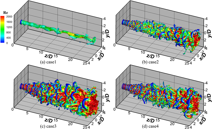
Figure 8 shows the iso-surfaces of
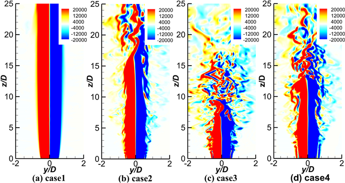
Figure 9 shows the x-direction vorticity in the y–z section of cases 1–4. It can also be seen that there is no rolling and breaking of the vortex although the values of vorticity are large for the case 1. After coflow argon jets are applied, the numbers of shear layers are increased from one to two, which are the shear layer between argon thermal plasma jet and coflow argon jet, and the shear layer between coflow argon jet and cold air, respectively. Two shear layers are separated at the jet upstream due to inlet boundary conditions and then merged with the development of the jet, in which the phenomenon of vortex rolling and breaking can be obviously observed. In addition, the intensity of this phenomenon increases with the increase of velocity and width in the coflow argon jet inlet. However, the flow inside argon thermal plasma jet is still very stable until the vortex breaking occurs at a certain location downstream. This location is affected by the velocity and width in coflow argon jet inlet, and increasing the velocity and width in coflow argon jet inlet can promote the transition of argon thermal plasma jet in advance.
The reasons of argon thermal plasma transition induced by coflow argon jet are investigated. The radial distributions of normalized axial velocity fluctuation
A numerical code solving argon thermal plasma jets flowing into cold air was embedded based on OpenFOAM. Compared with the laminar argon thermal plasma jet flowing into cold air, the effects of velocity and width in the coflow argon jet inlet on flow and mixing characteristics of thermal plasma jet have been studied by the large eddy simulation methods. The conclusions are summarized as follows:
(1) In comparison to the laminar argon thermal plasma jet flowing into cold air, the Kelvin–Helmholtz instability between thermal plasma jet and coflow argon jet is caused after the coflow argon jet is applied. As a result, a laminar jet transforms into turbulent jet. The length of argon thermal plasma jet reduces significantly, and the gradient of velocity and temperature enhances obviously in the downstream of jet.
(2) Increasing the width in the coflow argon jet inlet can create a dense argon atmosphere. On one hand, more coflow argon rather than ambient air is entrained into the upstream of thermal plasma jet. On the other hand, the specific enthalpy and specific heat of argon are much lower than those of air at the same temperature, causing the higher temperature in the upstream of argon thermal plasma jet.
(3) With the increase of velocity and width in the coflow argon jet inlet, the turbulent transport and coherent structure in the downstream of thermal plasma jet enhance. The mixing characteristics between argon thermal plasma, coflow argon and ambient air are also improved. In addition, the transition from laminar thermal plasma jets to turbulent thermal plasma jets can be advanced by increasing the velocity and width in coflow argon jet inlet.
This work is supported by National Natural Science Foundation of China (Nos. 12035015 and 12105282). The numerical simulations in this work have been performed on the supercomputers in the Supercomputing Center, University of Science and Technology of China.
| [1] |
Cheng K, Chen X and Pan W X 2006 Plasma Chem. Plasma Process. 26 211 doi: 10.1007/s11090-006-9006-6
|
| [2] |
Williamson R L et al 2003 Int. J. Heat Mass Transfer 46 4201 doi: 10.1016/S0017-9310(03)00272-2
|
| [3] |
Cheng K and Chen X 2004 Int. J. Heat Mass Transfer 47 5139 doi: 10.1016/j.ijheatmasstransfer.2004.06.028
|
| [4] |
Li H P and Chen X 2002 Plasma Chem. Plasma Process. 22 27 doi: 10.1023/A:1012988430995
|
| [5] |
Liu B et al 2008 IEEE Trans. Plasma Sci. 36 1076 doi: 10.1109/TPS.2008.924481
|
| [6] |
Xu D Y, Chen X and Cheng K 2003 J. Phys. D: Appl. Phys. 36 1583 doi: 10.1088/0022-3727/36/13/324
|
| [7] |
Gonzalez N Y M, El Morsli M and Proulx P 2008 J. Therm. Spray Technol. 17 533 doi: 10.1007/s11666-008-9209-x
|
| [8] |
Wang H X, Chen X and Li H P 2011 Plasma Chem. Plasma Process. 31 373 doi: 10.1007/s11090-011-9288-1
|
| [9] |
Wu G Q et al 2009 Int. J. Heat Mass Transfer 52 760 doi: 10.1016/j.ijheatmasstransfer.2008.07.043
|
| [10] |
Zhang T, Gawne D T and Liu B 2000 Surf. Coat. Technol. 132 233 doi: 10.1016/S0257-8972(00)00847-1
|
| [11] |
Planche M P, Liao H and Coddet C 2007 Surf. Coat. Technol. 202 69 doi: 10.1016/j.surfcoat.2007.04.053
|
| [12] |
Sobolev V V and Guilemany J M 1999 J. Therm. Spray Technol. 8 523 doi: 10.1361/105996399770350205
|
| [13] |
Gan J A and Berndt C C 2013 J. Therm. Spray Technol. 22 1069 doi: 10.1007/s11666-013-9955-2
|
| [14] |
Zeng Z, Kuroda S and Era H 2009 Surf. Coat. Technol. 204 69 doi: 10.1016/j.surfcoat.2009.06.036
|
| [15] |
Gawne D T, Zhang T and Liu B 2002 Surf. Coat. Technol. 153 138 doi: 10.1016/S0257-8972(01)01672-3
|
| [16] |
Kang K D and Hong S H 1999 J. Appl. Phys. 85 6373 doi: 10.1063/1.370140
|
| [17] |
Kim S et al 2010 Thin Solid Films 518 6369 doi: 10.1016/j.tsf.2010.03.154
|
| [18] |
Vadikkeettil Y et al 2018 Plasma Chem. Plasma Process. 38 759 doi: 10.1007/s11090-018-9890-6
|
| [19] |
Kai C et al 2006 Thin Solid Films 506 724
|
| [20] |
Mukherjee B et al 2019 ACS Appl. Mater. Interfaces 11 25500 doi: 10.1021/acsami.9b04239
|
| [21] |
Ranjan S et al 2020 J. Eur. Ceram. Soc. 40 660 doi: 10.1016/j.jeurceramsoc.2019.10.043
|
| [22] |
Boselli M et al 2013 J. Phys. D: Appl. Phys. 46 224009 doi: 10.1088/0022-3727/46/22/224009
|
| [23] |
Guo S F et al 2010 Plasma Chem. Plasma Process. 30 121 doi: 10.1007/s11090-009-9204-0
|
| [24] |
Peters J et al 2008 Plasma Chem. Plasma Process. 28 331 doi: 10.1007/s11090-008-9129-z
|
| [25] |
Islam A et al 2021 ACS Nano 15 1775 doi: 10.1021/acsnano.0c09451
|
| [26] |
Xu D Y, Chen X and Pan W X 2005 Int. J. Heat Mass Transfer 48 3253 doi: 10.1016/j.ijheatmasstransfer.2005.02.039
|
| [27] |
Williamson R L et al 2003 Int. J. Heat Mass Transfer 46 4215 doi: 10.1016/S0017-9310(03)00271-0
|
| [28] |
Pan W X et al 2001 Plasma Chem. Plasma Process. 21 23 doi: 10.1023/A:1007037327834
|
| [29] |
Huang P C, Hebeylein J and Pfender E 1995 Plasma Chem. Plasma Process. 15 25 doi: 10.1007/BF01596680
|
| [30] |
Wang H X et al 2008 Plasma Chem. Plasma Process. 28 85 doi: 10.1007/s11090-007-9109-8
|
| [31] |
Shigeta M 2019 IEEJ Trans. Electr. Electron. Eng. 14 16 doi: 10.1002/tee.22761
|
| [32] |
Shigeta M 2016 J. Phys. D: Appl. Phys. 49 493001 doi: 10.1088/0022-3727/49/49/493001
|
| [33] |
Shigeta M 2013 J. Phys. D: Appl. Phys. 46 015401 doi: 10.1088/0022-3727/46/1/015401
|
| [34] |
Shigeta M 2012 Plasma Sources Sci. Technol. 21 055029 doi: 10.1088/0963-0252/21/5/055029
|
| [35] |
Marchand C et al 2007 J. Therm. Spray Technol. 16 705 doi: 10.1007/s11666-007-9112-x
|
| [36] |
Jasak H, Jemcov A and Tukovic Z 2007 openfoam: a c++ library for complex physics simulations int. workshop on coupled methods in numerical dynamics (dubrovnik, croatia) (iuc) p 1
|
| [37] |
Zhou X et al 2021 Plasma Sci. Technol. 23 125405 doi: 10.1088/2058-6272/ac1f81
|
| [38] |
Murphy A B 1995 Plasma Chem. Plasma Process. 15 279 doi: 10.1007/BF01459700
|
| [39] |
Smagorinsky J 1963 Mon. Weather Rev. 91 99 doi: 10.1175/1520-0493(1963)091<0099:GCEWTP>2.3.CO;2
|
| [40] |
Murphy A B 1996 J. Phys. D: Appl. Phys. 29 1922 doi: 10.1088/0022-3727/29/7/029
|
| [41] |
Dinesh K K J and Kirkpatrick M P 2009 Comput. Fluids 38 1232 doi: 10.1016/j.compfluid.2008.11.015
|
| [42] |
Dinesh K K J et al 2012 Int. J. Heat Fluid Flow 33 193 doi: 10.1016/j.ijheatfluidflow.2011.10.007
|
| [43] |
Pfender E, Fincke J and Spores R 1991 Plasma Chem. Plasma Process. 11 529 doi: 10.1007/BF01447164
|
| [1] | Xu ZHOU, Xianhui CHEN, Taohong YE, Minming ZHU, Weidong XIA. Quasi-direct numerical simulations of the flow characteristics of a thermal plasma reactor with counterflow jet[J]. Plasma Science and Technology, 2023, 25(7): 075403. DOI: 10.1088/2058-6272/acb9d8 |
| [2] | Xu ZHOU (周旭), Xianhui CHEN (陈仙辉), Taohong YE (叶桃红), Minming ZHU (朱旻明). Large eddy simulation on the flow characteristics of an argon thermal plasma jet[J]. Plasma Science and Technology, 2021, 23(12): 125405. DOI: 10.1088/2058-6272/ac1f81 |
| [3] | Bo ZHANG (张波), Ying ZHU (朱颖), Feng LIU (刘峰), Zhi FANG (方志). The influence of grounded electrode positions on the evolution and characteristics of an atmospheric pressure argon plasma jet[J]. Plasma Science and Technology, 2017, 19(6): 64001-064001. DOI: 10.1088/2058-6272/aa629f |
| [4] | LI Guozhan(李国占), CHEN Fu(陈浮), LI Linxi(李林熙), SONG Yanping(宋彦萍). Large Eddy Simulation of the E?ects of Plasma Actuation Strength on Film Cooling Efficiency[J]. Plasma Science and Technology, 2016, 18(11): 1101-1109. DOI: 10.1088/1009-0630/18/11/08 |
| [5] | CAO Xiuquan (曹修全), YU Deping (余德平), XIANG Yong (向勇), YAO Jin (姚进), MIAO Jianguo (苗建国). Influence of the Laminar Plasma Torch Construction on the Jet Characteristics[J]. Plasma Science and Technology, 2016, 18(7): 740-743. DOI: 10.1088/1009-0630/18/7/07 |
| [6] | XU Qian(徐倩), DING Rui(丁锐), YANG Zhongshi(杨钟时), NIU Guojian(牛国鉴), K. OHYA, LUO Guangnan(罗广南). PIC-EDDY Simulation of Different Impurities Deposition in Gaps of Carbon Tiles[J]. Plasma Science and Technology, 2014, 16(6): 562-566. DOI: 10.1088/1009-0630/16/6/04 |
| [7] | HONG Yi (洪义), LU Na (鲁娜), PAN Jing (潘静), LI Jie (李杰), WU Yan (吴彦). Discharge Characteristics of an Atmospheric Pressure Argon Plasma Jet Generated with Screw Ring-Ring Electrodes in Surface Dielectric Barrier Discharge[J]. Plasma Science and Technology, 2013, 15(8): 780-786. DOI: 10.1088/1009-0630/15/8/12 |
| [8] | YANG Fei (杨飞), RONG Mingzhe (荣命哲), WU Yi (吴翊), SUN Hao (孙昊), MA Ruiguang (马瑞光), NIU Chunping (纽春萍). Numerical Simulation of the Eddy Current Effects in the Arc Splitting Process[J]. Plasma Science and Technology, 2012, 14(11): 974-979. DOI: 10.1088/1009-0630/14/11/05 |
| [9] | LV Xiaogui (吕晓桂), REN Chunsheng (任春生), MA Tengcai (马腾才), Feng Yan (冯岩), WANG Dezhen (王德真). An Atmospheric Large-Scale Cold Plasma Jet[J]. Plasma Science and Technology, 2012, 14(9): 799-801. DOI: 10.1088/1009-0630/14/9/05 |
| [10] | FEI Xiaomeng(费小猛), Shin-ichi KURODA, Yuki KONDO, Tamio MORI, Katsuhiko HOSOI. Influence of Additive Gas on Electrical and Optical Characteristics of Non- equilibrium Atmospheric Pressure Argon Plasma Jet[J]. Plasma Science and Technology, 2011, 13(5): 575-582. |
| 1. | Zhou, X., Chen, X., Ye, T. et al. Quasi-direct numerical simulations of the flow characteristics of a thermal plasma reactor with counterflow jet. Plasma Science and Technology, 2023, 25(7): 075403. DOI:10.1088/2058-6272/acb9d8 |
Figures(10) / Tables(3)
Supported by: Beijing Renhe Information Technology Co., Ltd. 
| Base case 1 | 600 | 13 000 |
DownLoad:
CSV
| Case | ||
| Case 2 | 20 | 0.5 |
| Case 3 | 50 | 0.5 |
| Case 4 | 20 | 1.16 |
DownLoad:
CSV
| Boundary | p | T | |||
| Thermal plasma jet inlet | Equation (10) | Equation (11) | |||
| Coflow argon jet inlet | Equation (12) | ||||
| Wall | |||||
| Other boundaries | p = 1 atm |
DownLoad:
CSV